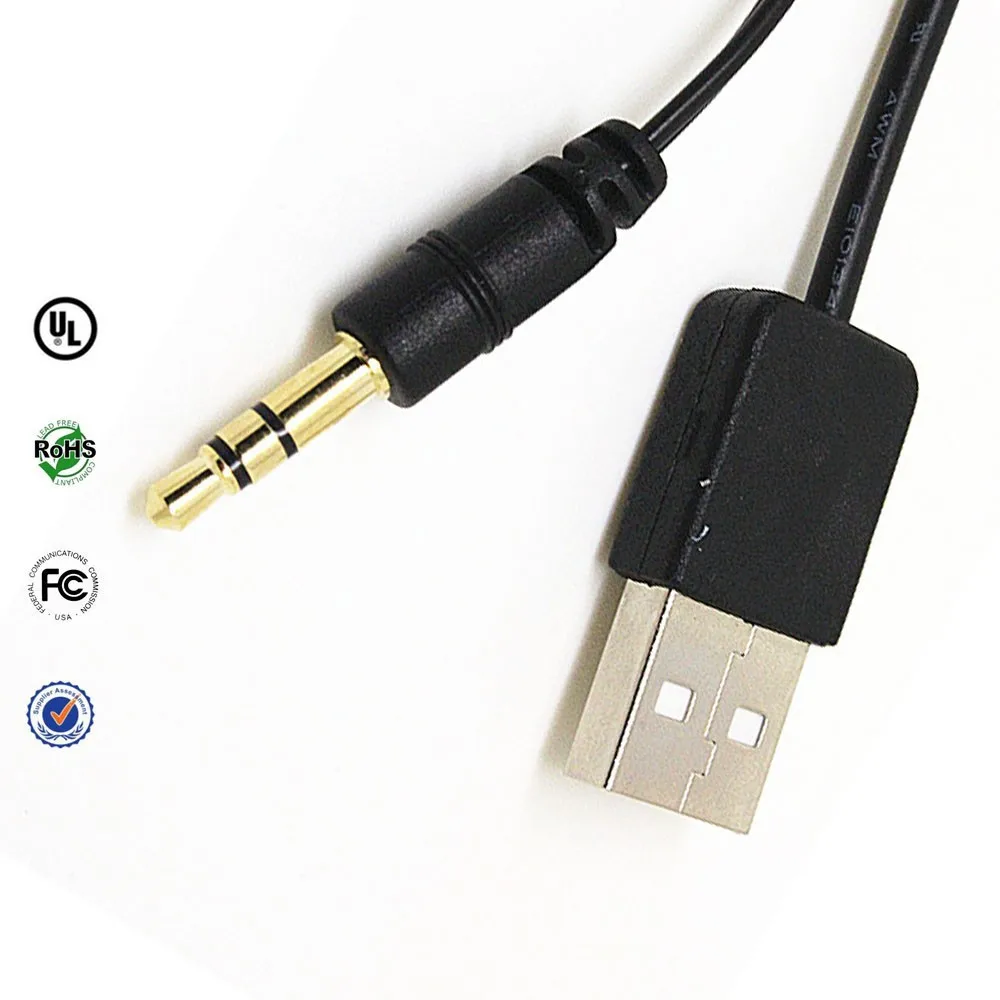
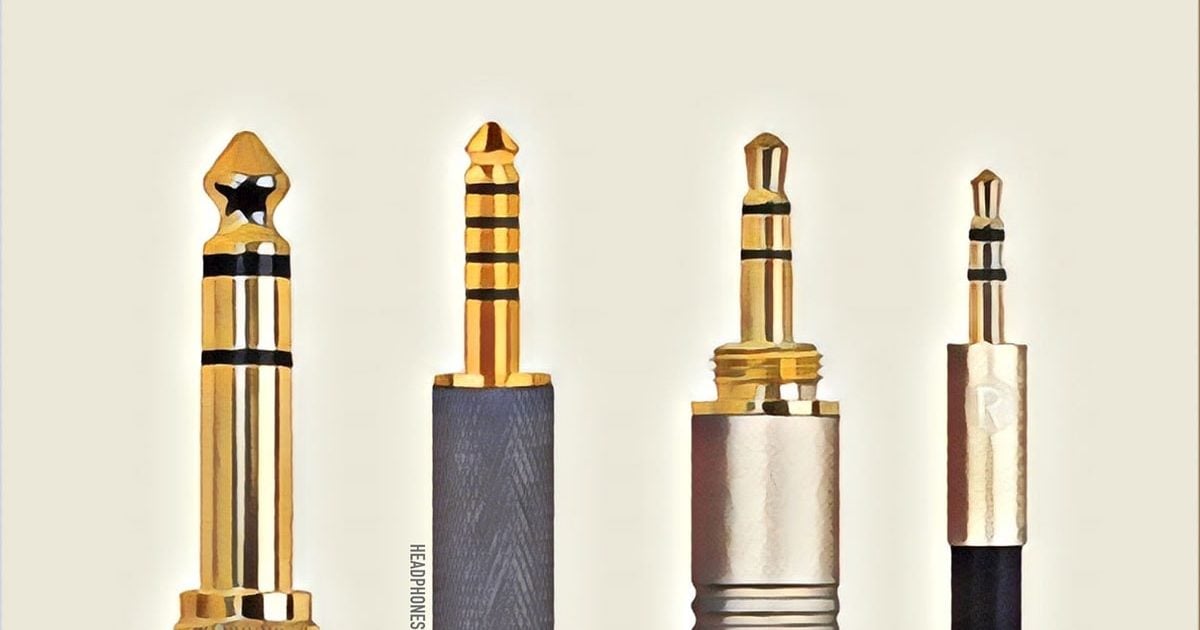
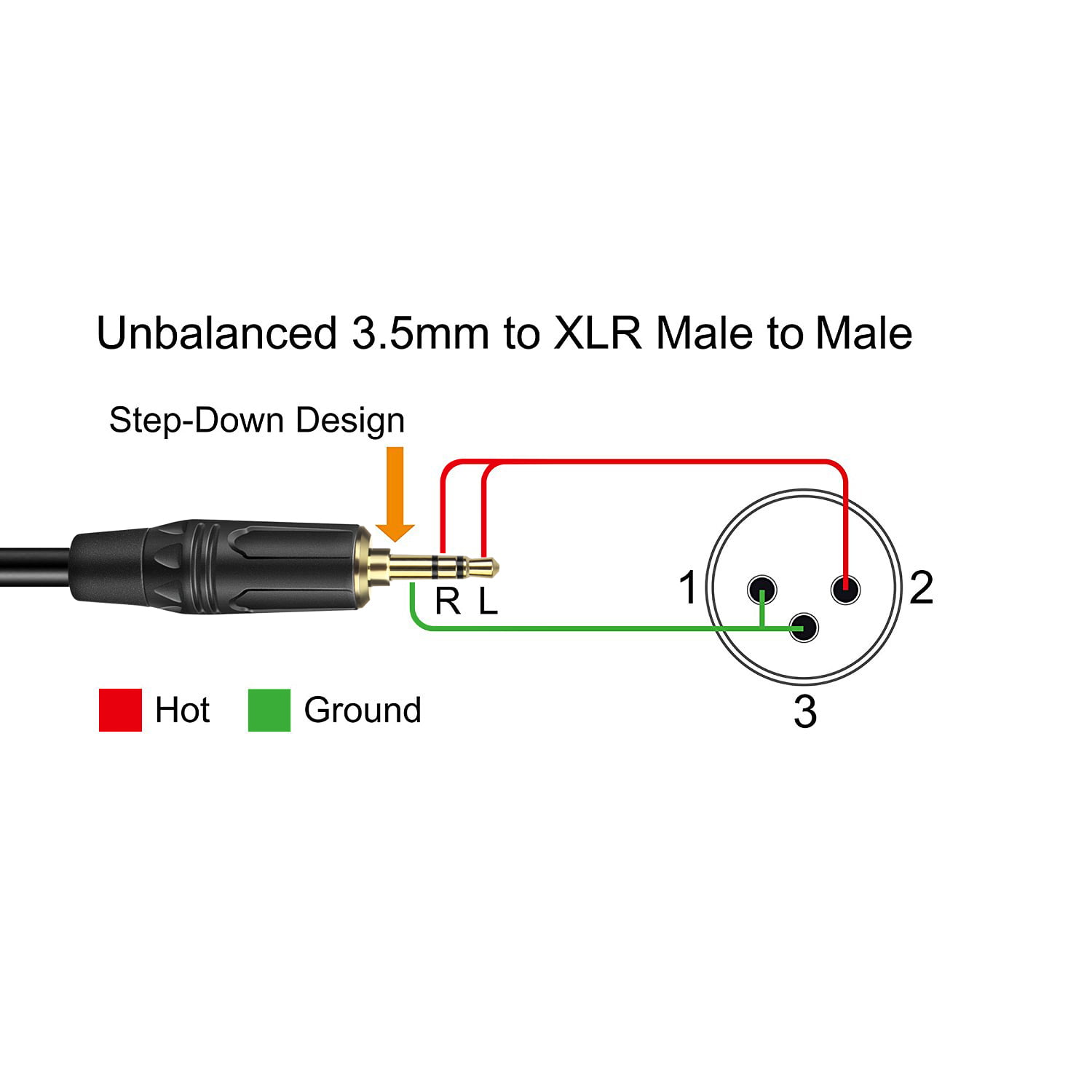
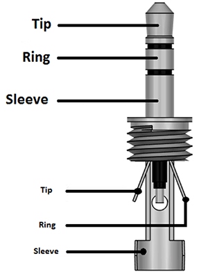
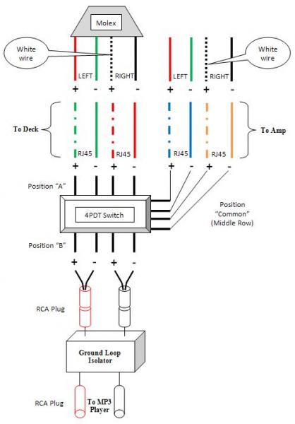
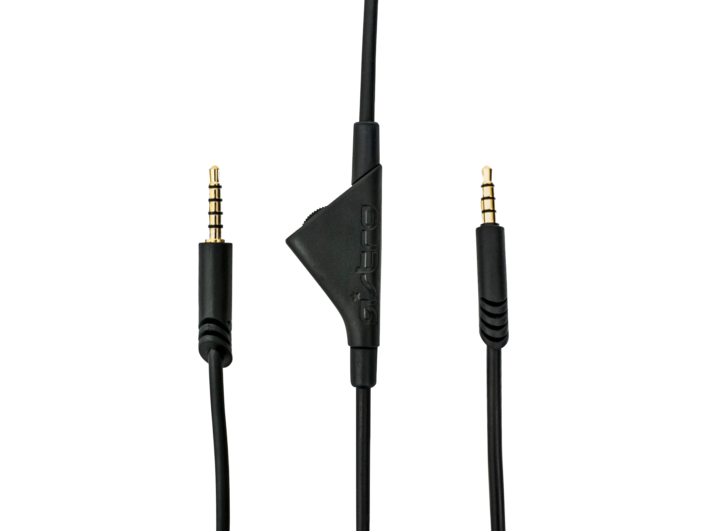
3 5mm audio jack wiring diagram u92au to 3 5mm wiring diagram usb mini to aux stereo 35mm make your own cable diy youtube diagram of usb to 35 mm jack adapter charging wiring uploaded by yamama on monday february 11th 2019 in category usb wiring diagram. Use the lighter to burn off the white insulation.
How To Hack A Headphone Jack
3 5 mm aux wiring diagram. It shows the components of the circuit as simplified shapes and the capacity and signal connections amongst the devices. 3 5mm plug wiring brass nickel plated plugs connect to 26 awg spiral wrapped copper shielded wire the dual conductor is shielded to protect against emi rfi interference the connectors are fully snagless to provide slim 3 5 mm connector for devices all metal connector housings for added durability easy coil wire for tangle free storage and travel during the pandemic and likely well afterward. In accordance with usb to 35 mm jack adapter wiring diagram there are only four wires used inside the cable. Now a days 35mm is the universal audio jack size to be found in smartphones pc and laptops. The red one is to get positive cable with dc power of 5 volts. It consists of instructions and diagrams for various types of wiring techniques along with other items like lights home windows etc.
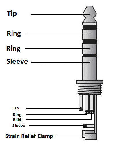
The little white wire inside the red and green wire is the mic ground. Also for hobbyists 35mm audio jack is a useful components for projects that plug into headphone jacks. 35mm audio jack wiring diagram wiring diagram name 4 pole 35mm jack wiring diagram wiring diagram contains numerous in depth illustrations that display the connection of assorted products. 3 5 aux plug wire diagram wiring library 4 pole 35mm jack wiring diagram furthermore wiring diagram provides you with the time frame by which the projects are to be completed. 35 mm stereo jack wiring diagram wiring diagram is a simplified gratifying pictorial representation of an electrical circuit. Black wire serves as floor just like in any other device.
Typically it uses black black red and white cable colors. If you are using a 35 mm audio plug from a pair of headphones then there are four wires coming from it. You may be capable to understand precisely when the projects should be accomplished that makes it easier for you to properly manage your time. The red and green wire which has the white wire inside it. Is the mic wire posn 4m on the diagram below. If you want to find the other picture or article about 35 mm jack wiring diagram 3 5.
For my headphones the right and left channels were in green and white insulation while the two grounds were bare copper wires. See also usb audio and usb type c headphones explained diagram of usb to 35 mm jack adapter. This is tricky to solder. Two are grounds for each of the rca plugs and one is the right channel and one is the left channel. Twist this ground together with the copper ground posn 3 gnd.
