To the terminals marked nc for fail safe devices and to no for fail secure devices. This diagram is to be used as reference for the low voltage control wiring of your heating and ac system.

Sync 1 To Sync 3 Conversion Feasability Study Thread
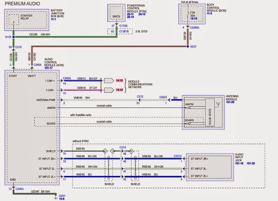
Acm 8 wiring diagram. Trying to find information about acm wiring diagram. Wiring diagram index name description page aa power distribution frc 3 ab power distribution frc 4 ac power supply circuit protection 34 ef 5 ad power supply circuit protection 44 ef 6 ae grounding 7 af starting and charging 8. Jump if needed to achieve correct cfm. 8 refer to the blower chart for cfm requirements. 8 output access power controller module converts one 1 12 to 24 volt ac or dc input into eight 8 fused power outputs individually selectable fail safe fail secure outputs or dry form in. Altronix acm8 converts one 1 12 to 24 volt ac or dc input into eight 8 independently controlled fuse protected outputs.
These power outputs can be converted to dry form c contacts. In fig19c note that there are small numbers along the right hand side of the diagram as well. The acm8 will provide either 8 wet 8 dry or any combination of both wet and dry outputs. You may be a professional that intends to search for referrals or fix existing troubles. Or you are a trainee or maybe even you who just need to know about acm wiring diagram. Place a jumper connecting y and o.
You are right here. Contacts fire alarm disconnect is selectable by output ul r must be a reseller to purchase this product. Wilbo666 2jz gte jzs147 aristo engine wiring size. Some ac systems will have a blue wire with a pink stripe in place of the yellow or y wire. Acm series access power controllers with power supplies installation guide models include. 092503 for a red enclosure add an r suffix to the part eg.
Al400ulacm al600ulacm 12vdc at 4 amp 12vdc or 24vdc at 6 ampor 24vdc at 3 amp fused outputs fused outputs al1012ulacm al1024ulacm 12vdc at 10 amp 24vdc at 10 amp fused outputs fused outputsrev. Now look at the lower portion of the wiring diagram in fig18 and locate the relay coils ifr and c1 on lines 52 and 57. Wiring diagram index 12v name description page name description page aa o power distribution 12 2 gd lighting forwardsignal cxugu7gu8 30. These numbers designate the line location of relay contacts. The acm8acm8e will provide either eight 8 switched power outputs eight 8 dry form c outputs or any combination of of both switched power and form c outputs plus eight 8 unswitched auxiliary power outputs. When using an ac power source polarity is not observed connect the neg of the device being powered to the terminal marked com and the pos.
B numbers on right hand side of the diagram. Outputs are activated by an open collector sink or normally open no dry trigger input from an access control system card reader keypad push button.


