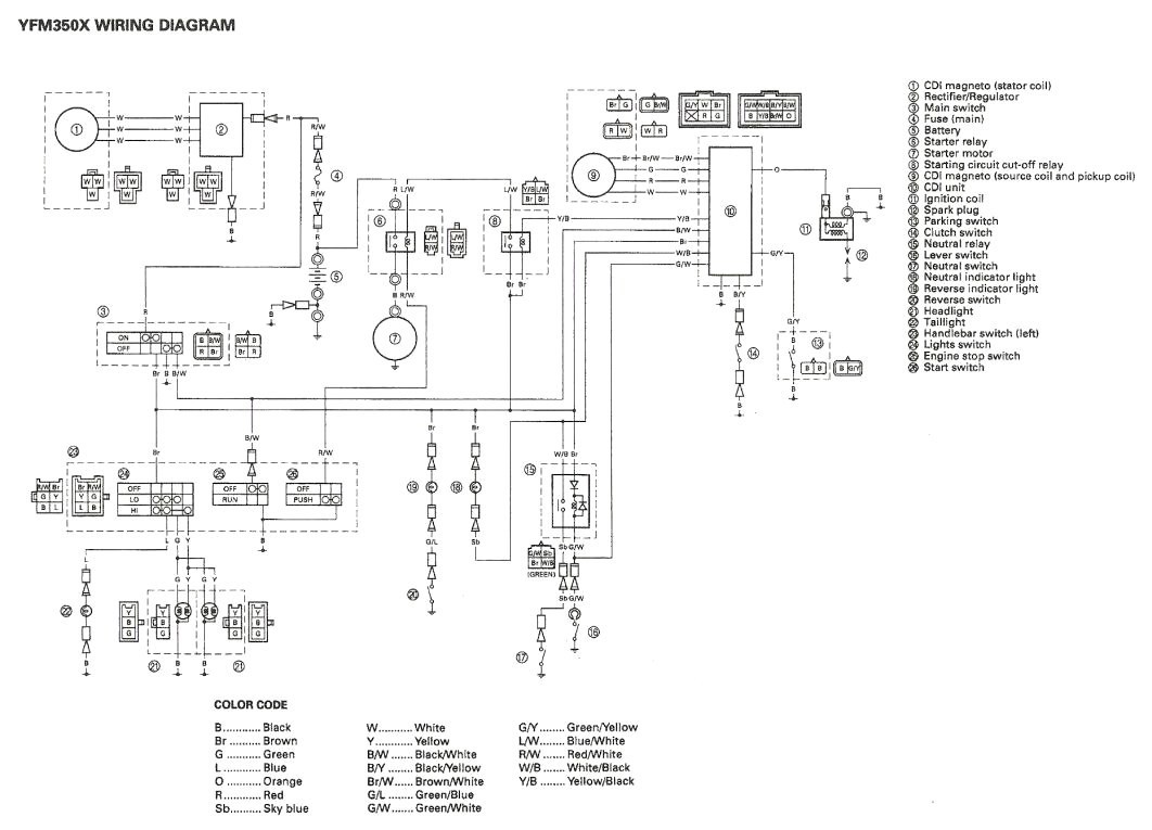
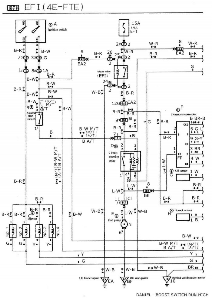
Blaster coil wiring diagram free image engine on yamaha blaster engine diagram full size of wiring sporty pin diagrams home also icapebub rh. Msd blaster 2 coil wiring diagram needed.

42db9 1986 Yamaha Cdi Wiring Diagram Wiring Library
Blaster wiring diagram. Yamaha blaster wiring diagram 1991 yamaha blaster wiring diagram 1996 yamaha blaster wiring diagram 2000 yamaha blaster wiring diagram 200cc every electrical arrangement is composed of various different parts. Alternatively the bike might be mapped too rich. Find great deals on ebay for yamaha blaster wiring in electrical components. Msd blaster ss coil wiring diagram wiring diagram is a simplified gratifying pictorial representation of an electrical circuit. Before attempting any wiring find which diagram illustrates your vehicles ignition system. Figure 1 using the wire splices.
Otherwise the structure will not function as it should be. Nopistons mazda rx7 size. Each part should be placed and connected with other parts in particular way. The obvious thing is the low price as always combined with our 1 year warranty. 2002 yamaha blaster wiring diagram. Figure 1 shows the correct procedure for these splices.
The blaster can only be used on inductive ignition systems. Shurflo water pump wiring diagram rv water pump switch wiring diagram rv water pump wiring diagram shurflo 12v water pump wiring diagram every electric arrangement consists of various unique components. It shows the components of the circuit as simplified shapes and the capability and signal contacts amongst the devices. Yamaha blaster stator wiring diagram encouraged in order to my personal blog in this occasion i will teach you regarding yamaha blaster stator wiring diagram. Instant download 1988 2006 yamaha blaster 200 ysf200 repair manuala yamaha blaster 200 atv repair manual is a book of instructions that guides the. Front brake 5 2 5 3 8 20 8 22 9 adjust if necessary.
Each component ought to be placed and linked to different parts in particular way. Dc viair dual compressor wiring diagram dc 380 viair dual 380c compressor wiring diagram dc 400 viair dual 400c compressor wiring diagram dc 450 viair dual 450c compressor wiring diagram dc 480 viair dual 480c compressor wiring diagram dc ob2 air zenith dual ob2 compressor wiring diagram. 800 x 600 px source. In the installation it is necessary to use the supplied wire splice devices. If not the structure wont work as it should be. 800 x 600 px source.


