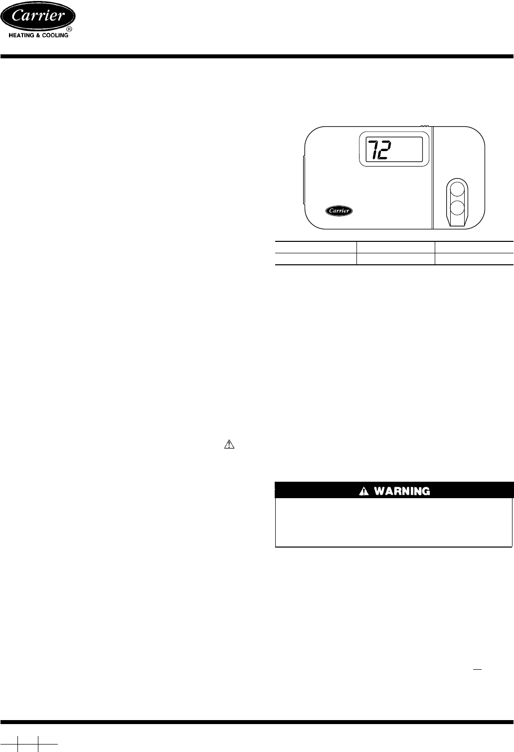
The thermidistat has a simple programmable interface and large intuitive buttons giving you easy control over indoor temperature and humidity plus fan speed and more. Carrier tstatccprh01 b 7 day programmable perfromance thermidistat control w outdoor sensor the performance thermidistat is more than a mere digital thermostat.

9268 1991 Subaru Legacy Wiring Diagram Wiring Resources
Carrier tstatccprh01 b wiring diagram. See table 6 and wiring diagrams fig. 12 2 stage furnace fig. 2 through 25 remember r and c must be connected for proper operation. Check to make sure wiring is correct before proceed ing with installation or turning on power. Push any excess wire into wall and against rear. 4 fk series fan coil fig.
Standard 18 to 22 gage. 40ru 25 30 01ss installation manual 40ru 25 30 01ss installation manualpdf 40ru 25 30 01ss installation manualpdf. The outdoor air temperature sensor must be used with the dual fuel thermostat. 8 1 stage furnace fig. It allows the temperature at a remote location outdoors to be displayed on the thermostat. 3 through 30 remember r and c must be connected for proper operation.
Improper wiring or installation may damage thermidistat control. View online or download carrier tstatccnhp01 b installation start up and operating instructions manual. 5 description builders model thermostats. Improper wiring or installation may damage thermidistat control. The performance edge programmable thermostat tp prh01 b offers relative humidity control and intelligent system management in a sleek design. Low voltage wiring diagrams wiring diagram reference chart equipment selection single speed air conditioner two speed air conditioner single speed heat pump two speed heat pump typical fan coil fig.
24vac nominal 18 to 30 vac 5060 hz wiring. Table of contents optimum performance is obtained when an outdoor temperature sensor is used with the thermidistat control. Cc carrier brand b builders model a99047 as an energy star sm partner. Outdoor temperature sensor is an accessory for all carrier electronic thermostats except the non programmable air conditioner version and builders thermostats. Push any excess wire into wall and against rear. See table 5 and wiring diagrams fig.
Check to make sure wiring is correct before proceed ing with installation or turning on power. Plan installation so that 2 wires can be run from thermidistat control to an outdoor location preferably on the north side of the house or refer to installation instructions included with the outdoor temperature sensor for simplified connection. Carrier tstatccnhp01 b pdf user manuals.
