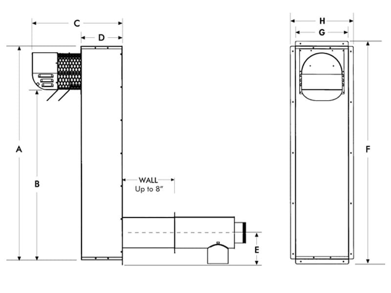
Search by combustion air treatment or ventilation. Ok ill do that i just wasnt certain how to do it based on the diagrams provided with the cas 4.

Wei Chen S Research Works Chinese Academy Of Sciences
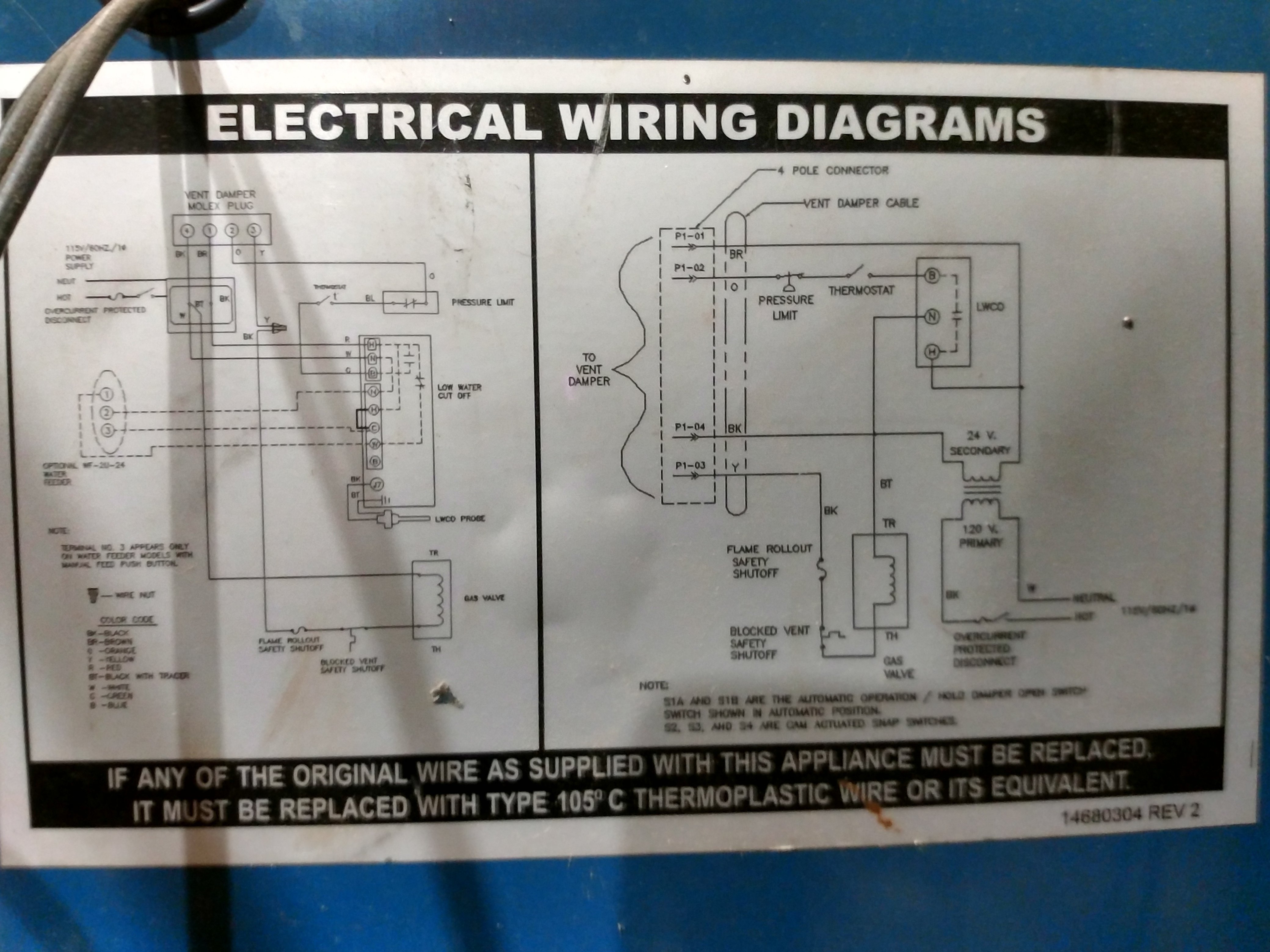
Field controls cas 4 wiring diagram. Only use for gas systems up to 280000 btum these models are designed to provide combustion air for appliances when direct connection to the burner is not possible when the appliance is located in a confined space. Cas 4 for gas heating appliances the fan in a can diffuses the outside air into the room near the burner to ensure adequate air for efficient combustion. I need to know how to wire a field controls model cas 4 combustion air intake fan unit to a weil mclain cga 6 boiler answered by a verified hvac technician i have the installation manual for the cas 4 but im not sure which diagram to follow. Items included in kit. Installation manual and wiring diagram for system control kit models ck 20f and ck 20fg for 30mv controlled natural or lp gas appliances with a pressure tap port in the gas valve. Field controls cas 4 fan in a can for gas systems 24v note.
I need to know how to wire a field controls model cas 4 combustion air intake fan unit to a weil mclain cga 6 boiler answered by a verified hvac technician. Wiring diagram for models cas 4 cas 4jr 6 7 and pvg chimney vent two 24 volt gas appliances with cac 24 combustion air controller. Ok the wiring schematic weil. Is designed for gas appliances up to 110000 btuhr input. 46284600 fan pdf manual download. The fan in a can jr model cas 4jr.
Rick hvac supervisor replied 4 years ago. Search the field controls wring diagram library for all wiring disgrams on field controls products. Cas 6 6sk 7 7sk installation manual wiring diagrams. It also has connections for the gas valve which has violet wires 110vac. Refer to diagrams a and b for guidance in setting up the cas system based on the size and length of the connecting ductwork and the input rating of the appliance. View and download field controls 46284600 manual online.
1 motorized blower 1 4 galvanized intake air vent hood 2 mounting brackets to secure the cas to a wall 2 wireconduit connectors 1 4 x 6 pipe increaser. Thanks rick i appreciate your time. According to nfpa 54 and nfpa 31 an engineered system such as a cas 3 4 6 or 7 may be used to overcome the. Ovd w bolier swg and cas 3 wiring diagram. Wiring diagram for ovd and honeywell r7184b p or u carlin 60200 02 and beckett genesis 7505 primary control. The cas 4 wiring diagram shows four thermostat connections on the appliance c g r w but the carlin control has just two terminals for the thermostat.
The cas 4 appears to need 24 volts to power its relay.


