Press the any button on the handset for 1 second. A wiring diagram mini manual schematic is packaged with each appliance.

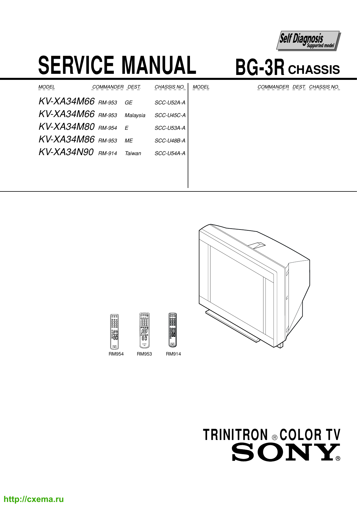
Service Manual Ge 1a Chassis
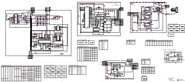
Ge rcv1 wiring diagram. Download 1849 ge air conditioner pdf manuals. Variety of ge stove wiring diagram. Wiring diagram book a1 15 b1 b2 16 18 b3 a2 b1 b3 15 supply voltage 16 18 l m h 2 levels b2 l1 f u 1 460 v f u 2 l2 l3 gnd h1 h3 h2 h4 f u 3 x1a f u 4 f u 5 x2a r power on optional x1 x2115 v 230 v h1 h3 h2 h4 optional connection electrostatically shielded transformer f u 6 off on m l1 l2 1 2 stop ol m start 3 start start fiber optic. Hand set programming press the learn button on the receiver device for 1 second led will light up. Ge 10t1 rider tv5 ge 12c107 sams 125 7 ge 15cl100 wallace ge 17t10 sams 196 3 ge 21c115 21t14 sams 229 7 ge 27gt530 ge 27gt630 ge 27gt716 ge 27gt720tx1 service manual ge 31gt720 ge 31gt750 service manual ge 46gw948 service manual ge 46gw948yx8 service manual ge 800 rdier tv4 ge 801 rider tv1 ge 802 oper. The diagram may be mailed or e mailed.
It reveals the components of the circuit as streamlined forms and the power as well as signal links between the tools. Red wire black yellow or blue 12v dc ov dc ground trigger momentary no 3. A wiring diagram is a simplified standard pictorial representation of an electric circuit. Some window air conditioners dehumidifiers compact refrigerators and small countertop microwaves do not have wiring diagrams. You can reach us by dialing 1. Reference to the following wiring diagram.
Ge diagrams schematics and service manuals download for free. If you cannot locate your wiring diagram you can call the appliances answer center with your complete model number. Serwis 48 513 153 944. Universal receiver ge rcv1 instruction wwwpeiterpl 96 500 sochaczew ul. Refrigerator wiring diagram location freezer wiring diagram location ice machine wiring diagram location. The most common locations for the wiring diagram is listed by product line below.
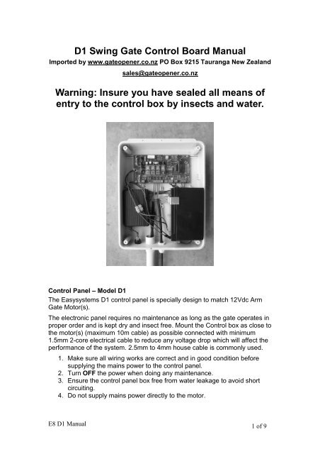
Setting the 12v dc remote control handset ge rcv1 2. Connect cable as follows. 3 channel relay correspond the first the second and the fourth button of the. 15 go sierpnia 33a telfax 48 46 862 34 88 tel. User manuals ge air conditioner operating guides and service manuals. 3ø wiring diagrams 1ø wiring diagrams diagram er9 m 3 1 5 9 3 7 11 low speed high speed u1 v1 w1 w2 u2 v2 tk tk thermal overloads two speed stardelta motor switch m 3 0 10v 20v 415v ac 4 20ma outp uts diagram ic2 m 1 240v ac 0 10v outp ut diagram ic3 m 1 0 10v 4 20ma 240v ac outp uts these diagrams are current at the time of publication.


