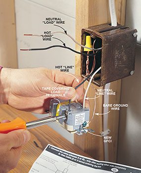
Two wire cable is run between the gfcis and the hot and neutral wires from the source are spliced to the line terminals at each device. If more than 1 black and 1 white conductor are in the electrical box also loosen the load side silver and brass terminal screws.
United Kingdom Gfci Receptacle Wiring Diagram Hondadr Alpa
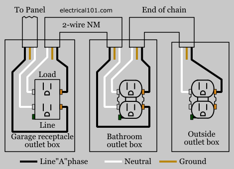
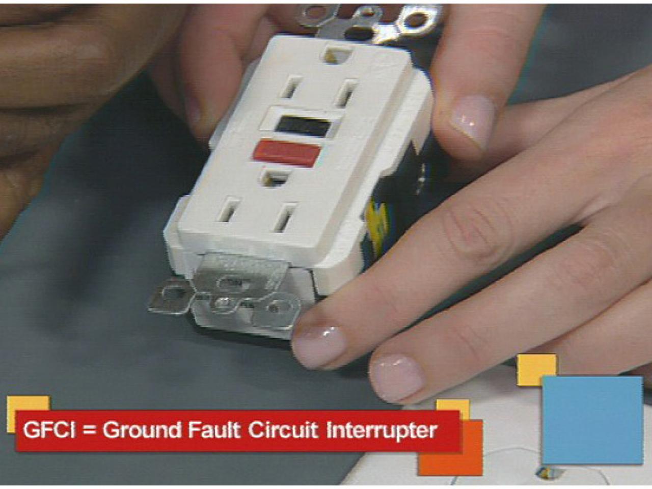
Ground fault receptacle wiring diagram. Arc fault circuit interrupters afcis replace an electrical outlet. So gfci designed as checking the difference between the current leaving and returning through current transformer of the gfci to protect device exceeds 5ma. Eatons ground fault circuit interrupter gfci receptacles are circuit interrupters designed to recognize a ground fault in your wiring and immediately break the flow of electricity thus protecting you from electrical shock. Ground fault circuit interrupters gfcis gfci load wiring. Just click the wiring diagrams wiring a gfci outlet with a switch how to wire a gfci outlet with a switch there are a few different methods that are used to. In this diagram multiple ground fault circuit interrupter receptacles are wired together using pigtails to connect the source.
The load terminals on the gfci are not used and the last receptacle is wired directly to the circuit source. Eaton gfcis are tested to the highest standards and provide. A wiring diagram is a simplified standard photographic representation of an electrical circuit. Refer to the diagram above about wiring gfci receptacles for additional help. Gfci receptacle in a series with an unprotected outlet this diagram illustrates the wiring for multiple ground fault circuit interrupter receptacles with an unprotected duplex receptacle at the end of the circuit. Gfci outlet wiring diagram.
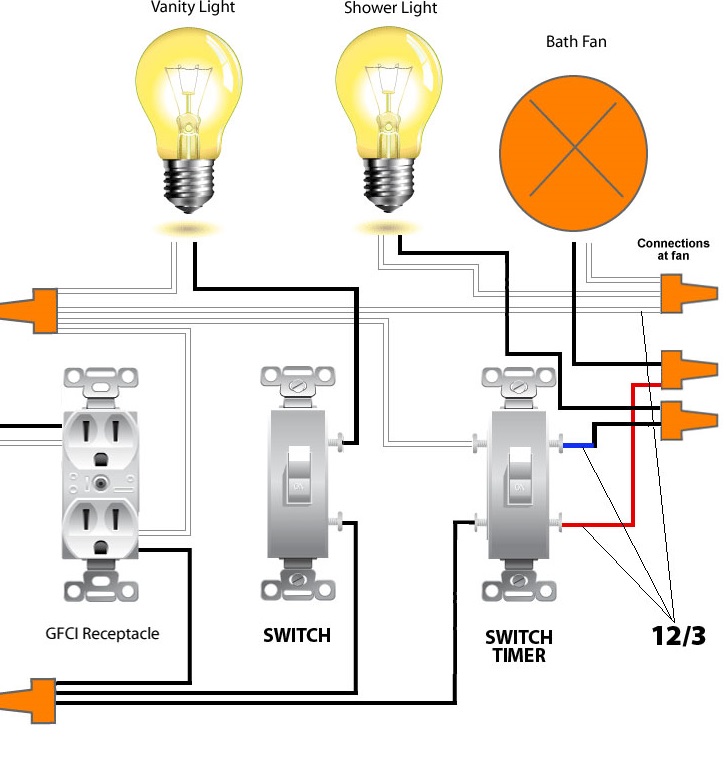
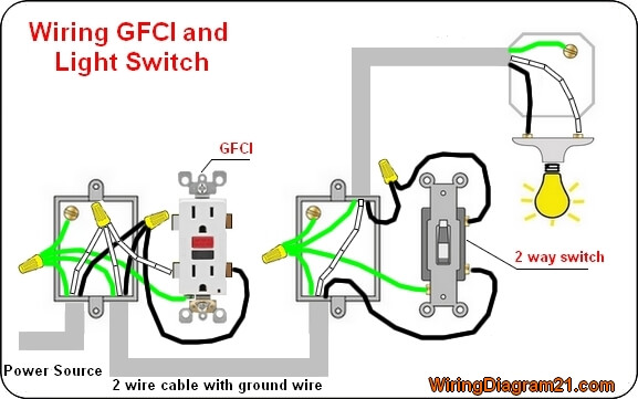
Loosen the silver and brass terminal screws on the line side of the outlet. It shows the components of the circuit as streamlined shapes and the power as well as signal connections in between the devices. In the gfci mainly two wires connect as also shown in a diagram the current flowing from the source and coming back are some due to current laws. In this gfci outlet wiring and installation diagram the combo switch outlet spst single way switch and ordinary outlet is connected to the load side of gfci. The toggle switch in the combo switch outlet controls the first light bulb while the single way. Further they prevent resetting if once tripped the ground fault renders the device no longer functional.
Just click the wiring diagrams wiring a gfci outlet with a switch how to wire a gfci outlet with a switch there are a few different methods that are used to wire gfi outlets but all start with locating the line side of the gfci receptacle where the power source is attached as described. Fully explained wiring instructions complete with a picture series of an installation and wiring diagrams can be found here in the gfi and light switch area here in this website. Wiring diagram for multiple gfcis. It means all the connected loads to the load terminals of gfci are protected. Collection of ground fault receptacle wiring diagram. The wiring diagram also shown below as follow.
Gallery of Ground Fault Receptacle Wiring Diagram