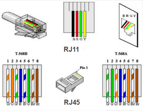
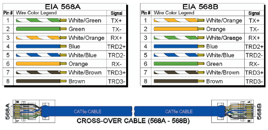
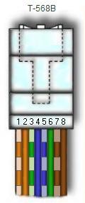
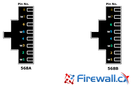
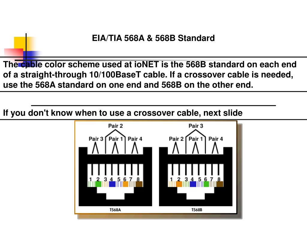
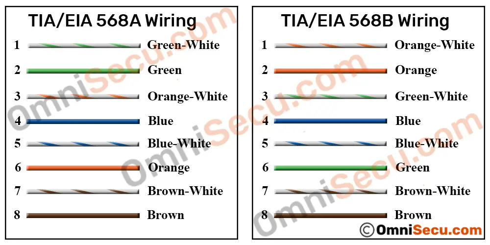
The first revision of the standard tiaeia 568 a1 1991 was released in 1991. If you compare the pin functions of both scheme a t568a and scheme b t568b you will find that they are the same and only the wiring colours are different.

Straight Through Cables Vs Crossover Vs Rollover Learn The
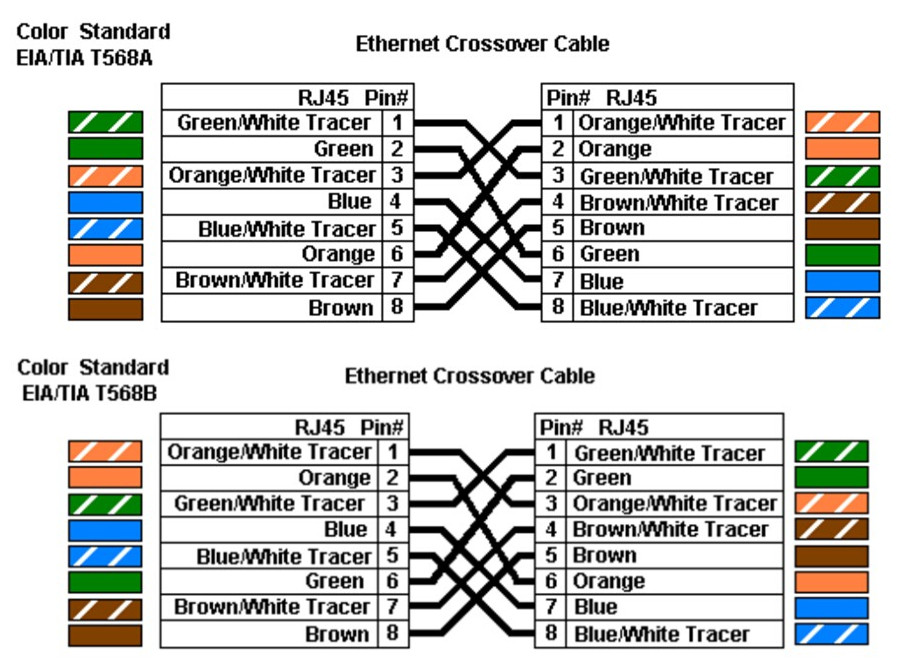
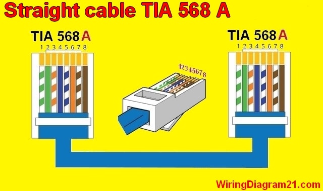
Tia eia 568b standard wiring diagram. Ethernet cable is to wire one end using the t 568a standard and the other end using the t 568b standard. This cabling guide highlights the differences between these wiring standards. Another way of remembering the color coding is to. And ensure all connectors and cables are modified in accordance with tia standards. Rj45 wiring diagram of eiatia 568b ethernet cable the pin description and names are the same as that for eiatia 568a ethernet cable. Tiaeia 568 b1 2001 is likely the most commonly used and talked about feature of the specification created in 1988.
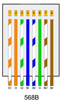
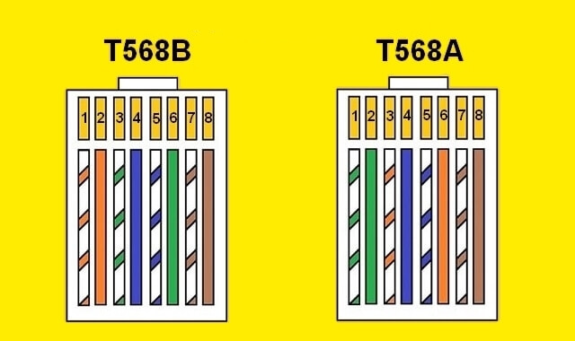
Rj45 wiring diagram t568b standard wiring scheme b or t568b is used for rj45 wiring and utilises different wiring colours to scheme a or t568a. Specifically switch the solid green gwith the solid orange and switch the greenwhite with the orangewhite. The t 568a standard and the other end using the t 568b standard. The 568a and 568b standards were developed to provide more effective communications for longer distances in a cat5e cable segment than using non standard schemes. Ansitiaeia 568 b3 optical fiber standards optical fiber cabling components addendums ansitiaeia 568 b1 1 patch cord bend radius ansitiaeia 568 b1 2 grounding bonding ansitiaeia 568 b1 3 supportable distances for optical fiber ansitiaeia 568 b1 4 recognition of category 6 850 laser optimized 50125µm multimode optical fiber. 568 a is the definition of pin assignments for the the pairs within category 3 cat3 category 5 cat5 and category 6 cat6 unshielded twisted pair utp cables eight conductor 100 ohm balanced twisted pair cabling.
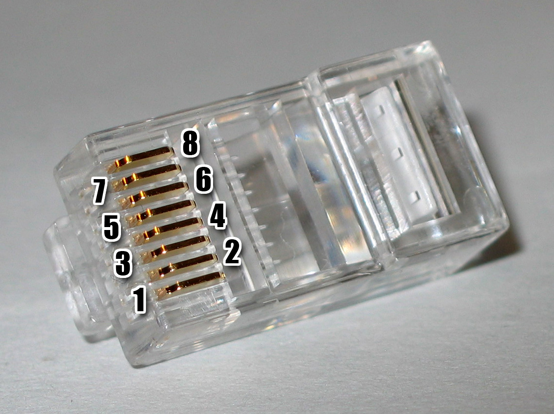
568 b wiring diagram 568b wiring diagram tiaeia 568b standard wiring diagram every electric structure is composed of various distinct components. Each part should be set and linked to different parts in specific way. Another way of remembering the colour coding is to simply switch the green set of wires in place with the orangeset of wires. Color code standards. For optimal performance a single cable has to be used for pins 1 and 2 pins 3 and 6 pins 4 and 5 and pins 7 and 8. It also provides insight for the steps involved in creating standard and crossover cables.
But the position of the different colored wires varies for both. The demands placed upon commercial wiring systems increased dramatically over this period due to the adoption of personal computers and data communication networks and advances in those technologies. Rj45 colors wiring guide diagram tiaeia 568 ab. If not the structure wont function as it ought to be. T 568a and t 568b are the two wiring standards for rj 45 connector data cable specified by tiaeia 568 a wiring standards document. The standard was updated to revision b in 1995.
The difference between the two is the position of the orange and green wire pairs.



.jpg)
