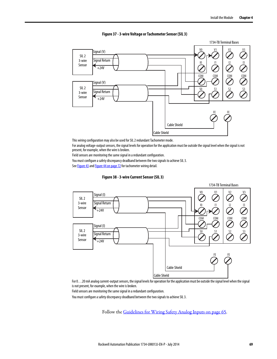
Provides installation information about 1734 tb and 1734 tbs assemblies point io wiring base assembly installation instructions publication 1734 in013 provides installation information about 1734 tb3 and 1734 tb3s. Ie2c analog current input module wiring diagram.

1203 Cn1 Allen Bradley Controlnet To Scanport Communication
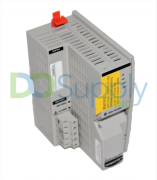
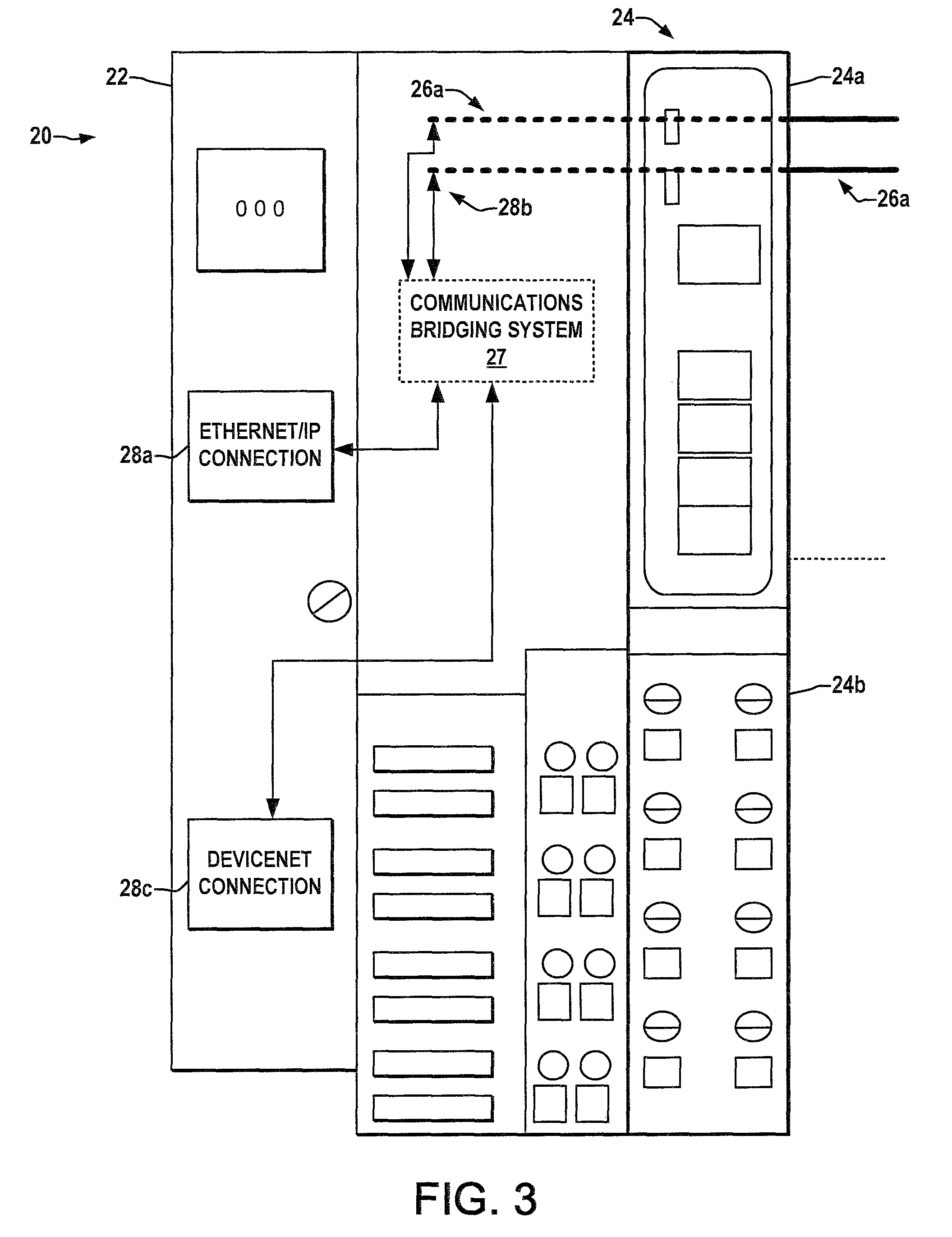
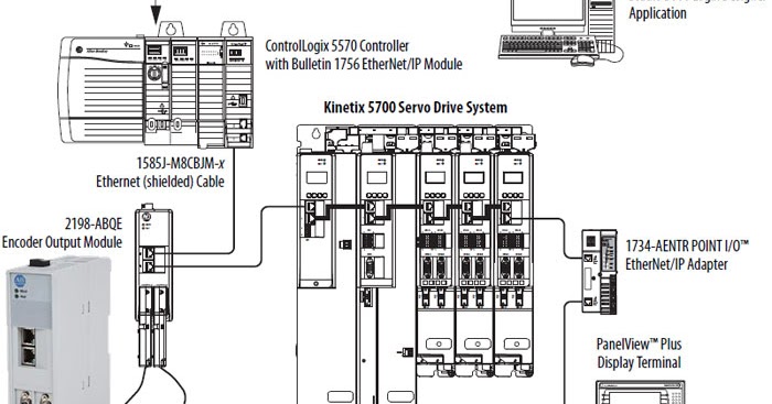
1734 aentr wiring diagram. Ow2 modules with load powered by internal power bus wiring diagram. With respect to use of information circuits equipment or software described in this manual. Rslogix 5000 version 17 or greater must be used for the 1734 aentr add on profile. 1734 aentr wiring diagram 29112018 29112018 6 comments on 1734 aentr wiring diagram aent aentr aentr aent comm e the examples and diagrams in this manual are included solely for illustrative purposes. The 1734 aentr adapters will accept io connections with the electronic keying for the 1734 aent. A b ow4 24vdc no dpst 4rly mod.
This manual is a reference guide for the aentr aentr series b. 6 point io 4 channel analog current output module publication 1734 in034d en e december 2018 attention. This allows the 1734 aentr adapter to be used in a daisy chain topology with the 1734 aent profile used for the 1734 aentr. 1734 in583 point io wiring base assembly point io wiring base assembly installation instructions 1734 in013. Ov8e ow2 ow4 ox2 ie2c ie2v oe2c oe2v. Ow4 codale item no.
Our partnernetwork offers complementary product solutions for 1734 point io modules and 1734 point io add on profiles through the encompass product reference program. The examples and diagrams in this manual are included solely for illustrative purposes. Point io synchronous serial interface absolute encoder module 1734 um007 point io cold junction compensation wiring base assembly point io cold junction compensation wiring base assembly 1734 in583 point io wiring base assembly point io wiring base assembly installation instructions 1734 in013. If this equipment is used in a manner not specified by the manufacturer the protection provided by the equipment may be impaired. No patent liability is assumed by rockwell automation inc. 26 install point io modules.
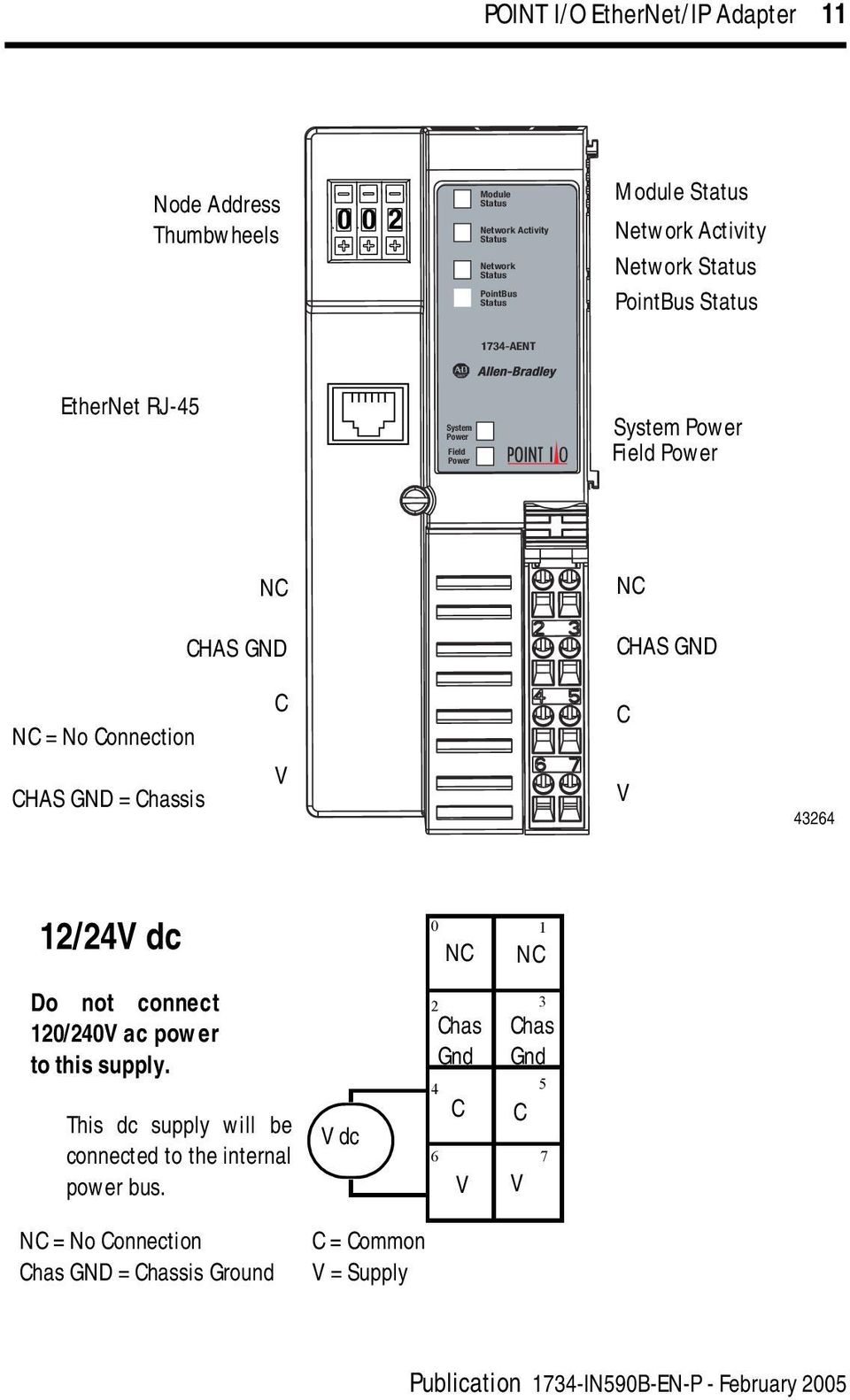
Because of the many variables and. You can sort and filter products from best in industry suppliers in your region to connect to the rockwell automation architecture or to use with our products. Wiring diagram module locking mechanism io module wiring base rtb rtb removal handle din rail locking screw orange 2 point io publication 1734 in510b en p august 2000 wiring diagrams v dc nc c v nc chass gnd c v daisy chain power out to modules 1224v dc power nc no connection chass gnd chassis ground c common v supply. Wiring diagram wiring diagram dwg 3 dimensional. Read this document and the documents listed in the additional resources section about installation configuration and operation of this. Allen bradley 1734 aentr wiring diagram the examples and diagrams in this manual are included solely for illustrative allen bradley rockwell automation armorpoint controllogix logix.
Ow2 and ow4 relay output modules.

