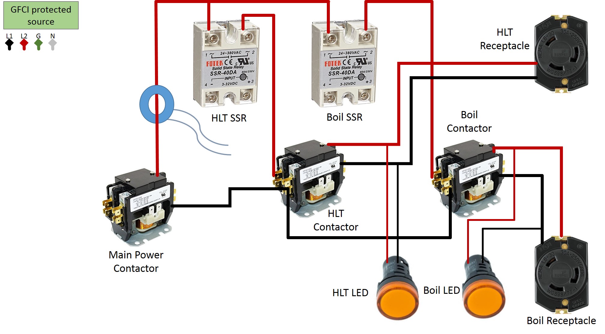
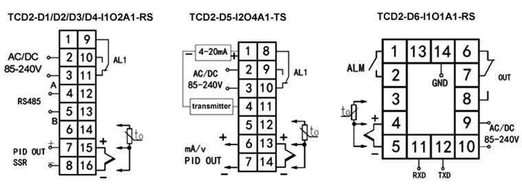
We then wire the output terminals on the pid to the ssr as if the pid was always ssr compatible. Variety of 240v motor wiring diagram single phase.

Xt 1883 110v Plug Wiring Diagram On 120v Pid Controller
240v pid controller wiring diagram. Wiring a 120 volt 20 amp pid controller duration. The solid state relay or ssr is essentially a switch with no moving partsby using a small trigger voltage from the pid it is able to switch a much larger voltage 240vac from the wall. Wiring a 240 volt 20 amp pid controller duration. A wiring diagram is a simplified standard photographic representation of an electric circuit. I want to buy or build one much like the kegking temp controller but with a pid controller instead of the stc style one. The pid im using has a built in ssr but it is only able to switch up to 3a of current as im running on 240v that limits me to around 700w.
Building a 240 volt 20 amp pid controller step by step part 2 duration. Wiring a 120 volt 20 amp pid controller duration. Collection of pid temperature controller wiring diagram. One final note is that you will need to configure the pid controller to reduce the cycle time to around 2 seconds which is often the minimum on relay output pids since rapid cycling of the mechanical relay will quickly cause it to fail. Barley and hops brewing 13562 views. It reveals the components of the circuit as simplified shapes as well as the power and also signal connections in between the tools.
Barley and hops brewing 5655 views. A wiring diagram is a streamlined conventional pictorial depiction of an electric circuit. It reveals the components of the circuit as streamlined shapes and the power and also signal connections in between the devices. Trolled around a bit but couldnt find any simple wiring diagrams for a pid controller with a probe and the necessary in and outor heat and cool power sockets. Heres the keg king one.


