Rq series. Packaged rooftop units heat pumps outdoor air handling units.

Aaon Air Handler Fan Motor Transformers Keep Tripping Unit
Aaon wiring diagram. Electrical wiring representations are comprised of 2 points. Warning warning statements are given to prevent actions that could result in. 901 wiring diagrams installation unit specific wiring diagrams are laminated and affixed inside the controls compartment aaon equipment has been designed for door. Caution caution statements are given to prevent actions that may result in equipment damage property damage or personal injury. Quick and easy installation. A wiring diagram is a kind of schematic which utilizes abstract photographic symbols to show all the affiliations of components in a system.
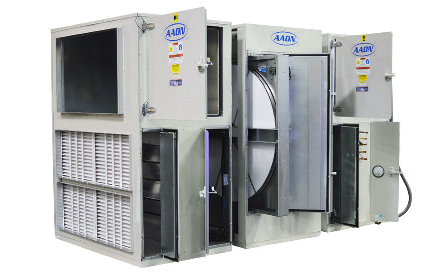
8 aaon rn series features and options introduction energy efficiency direct drive backward curved plenum supply fans two step variable capacity and variable speed r 410a scroll compressors airside economizers factory installed aaonaire energy recovery wheels double wall rigid polyurethane foam panel construction r 13 insulation. View and download aaon rn series installation operation maintanance manual online. Note notes are intended to clarify the unit installation operation and maintenance. Rq series packaged rooftop systems from 2 6 tons. Aaon rq series features and options introduction energy efficiency direct drive backward curved plenum installation and maintenance supply fans clogged filter switch variable capacity r 410a scroll color coded wiring diagram compressors compressors in isolated compartment. It reveals the components of the circuit as streamlined forms and the power as well as signal links between the tools.
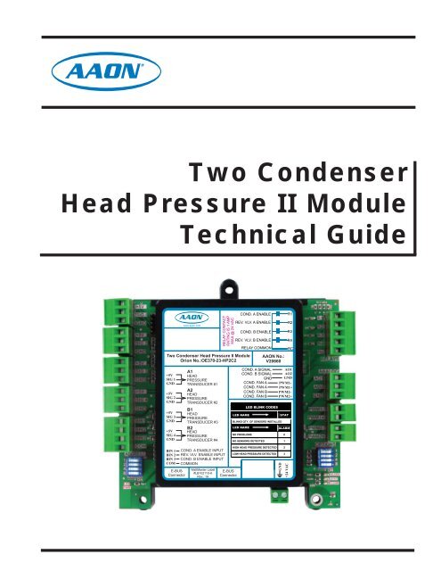
Rq series iom 16 mb electronic startup form model numbers beginning with rq 002 rq 003 rq 004 rq 005 or rq 006. Icons that represent the parts in the circuit as well as lines that represent the links between them. Example wiring diagram showing wattmaster refrigeration system module for variable speed compressors copeland inverter electronic expansion valve and variable speed condenser fan control. Condensate drain pan locating units unit requires drain traps to be connected to the curb should be mounted first and must the condensate drain pan of. Assortment of aaon rk series wiring diagram. Connect power and control wiring to the unit as shown in figure i12 and in the unit specific wiring diagram which shows factory and field wiring and is attached to the inside of the door of.
8 safety attention should be paid to the following statements. A wiring diagram is a streamlined traditional photographic depiction of an electrical circuit.


