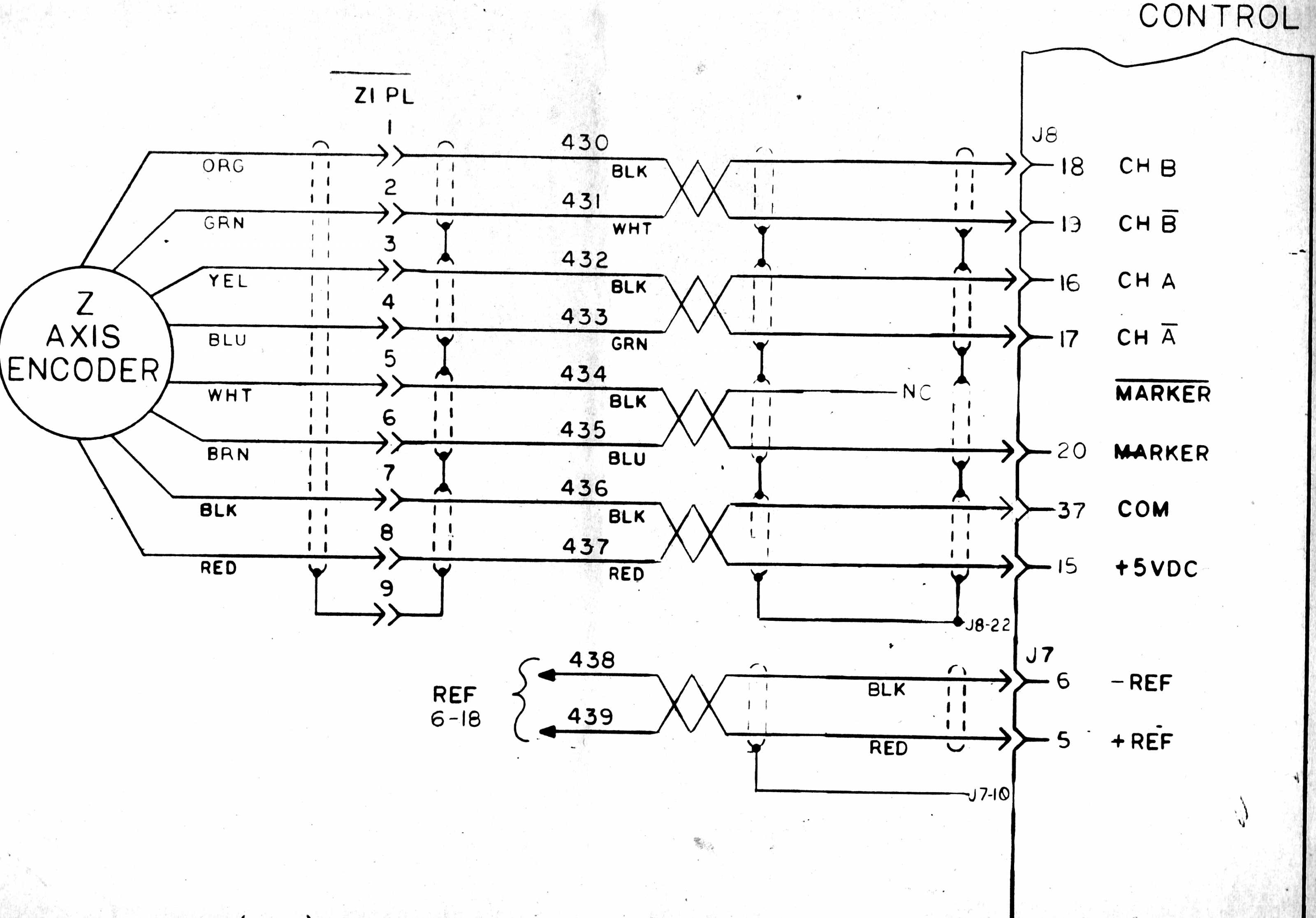
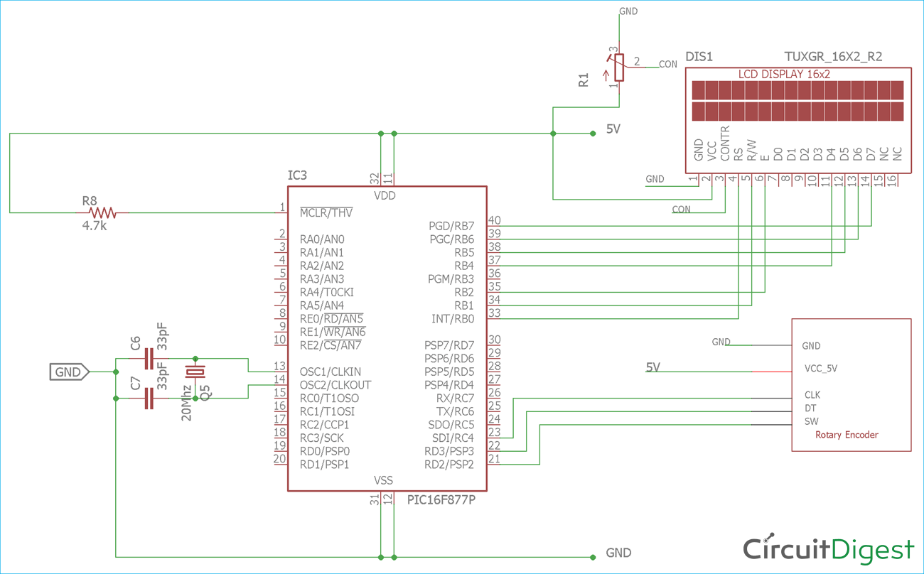
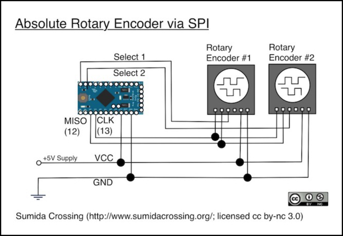
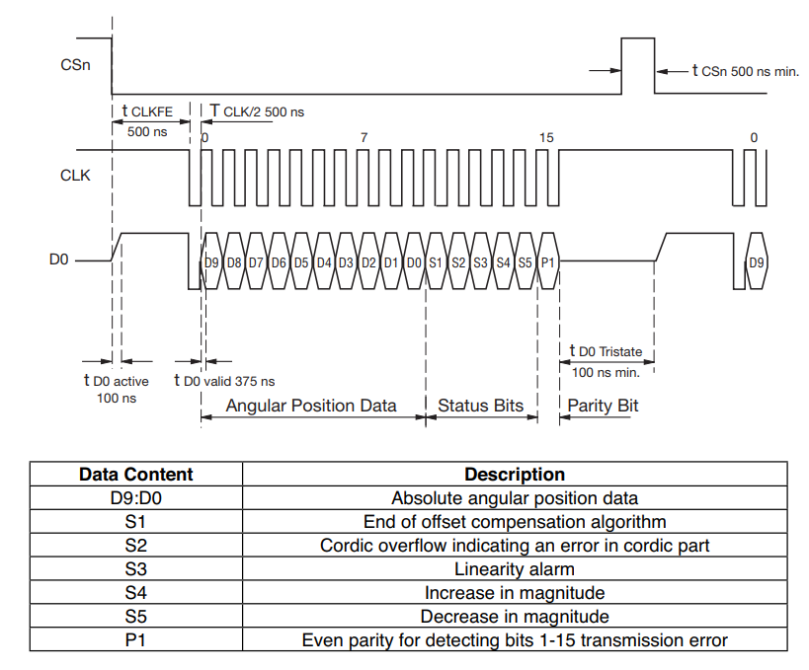
By providing auxiliary feedback directly through an ethernetip network these encoders eliminate the need for point to point wiring. When considering how to wire an absolute encoder the required resolution level of application control flexibility and ease of implementation all factor into the decision.

Feedback Connections Jupiter
Absolute encoder wiring diagram. Installation guides for rotary encoders absolute encoders incremental encoders as well as our motor mount and magneto encoder products. Installationinstructions bulletin842a absolute encoders important. Our magnetic encoders directly connect to devicenet for advanced functionality with reduced wiring cost. The h25 absolute encoder is available with the following certification. Dynapar complete encoder product manuals. Our ethernetip absolute encoders are designed with an embedded ethernetip switch and dual ethernet ports to support linear networks and device level ring topologies.
Gc gray code. The examples and diagrams in this manual are included solely for. Ms3112e14 19p 19pin connector on encoder body mates to ms3116j14 19s or equivalent notes tables. Encoders provide motion control systems information on position count speed and direction. Ethernetipabsolute encoder catalog numbers 842e sip1ba. 842e sip2ba 842e sip3ba 842e sip4ba 842e sip5ba 842e sip6ba 842e sip7ba.
Specifications electrical codeformat gray ornatural binary codedirection cw or ccw symmetry 40 to 60 operating voltage 1032v dc power requirements 150ma at 5v no load max ofstepsrevolution 8192 max ofrevolutions 8192 position forming time 05msec delay on power up 1050msec. Encoder wiring schemes can be unique to each encoder and one should follow the diagram or pinout designated on the encoder datasheet. Save these instructions for future use. En 55011 and en 61000 6 2 code type. All notes and tables referred to in the text can be found on the back of this page. Familiarize themselves with installation and wiring instructions in addition to requirements of all applicable codes laws.
Absolute encoders retain your position data during loss of power. Wiring an encoder is parallel is the most straightforward method and is the standard for single turn encoders. The signal may be in the form of a square wave for an incremental encoder or an absolute measure of position for an absolute encoder. They are excellent choices in systems that require failsafe operation. As the encoder shaft rotates output signals are produced proportional to the distance angle of rotation. Multi channel differential encoder wiring with commutation tracks can have up to 14 wires and miswiring can result in signal issues such as deformed pulses low signal amplitude and shorted connections.


