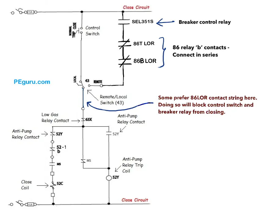
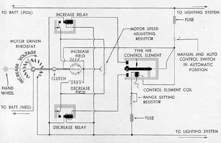
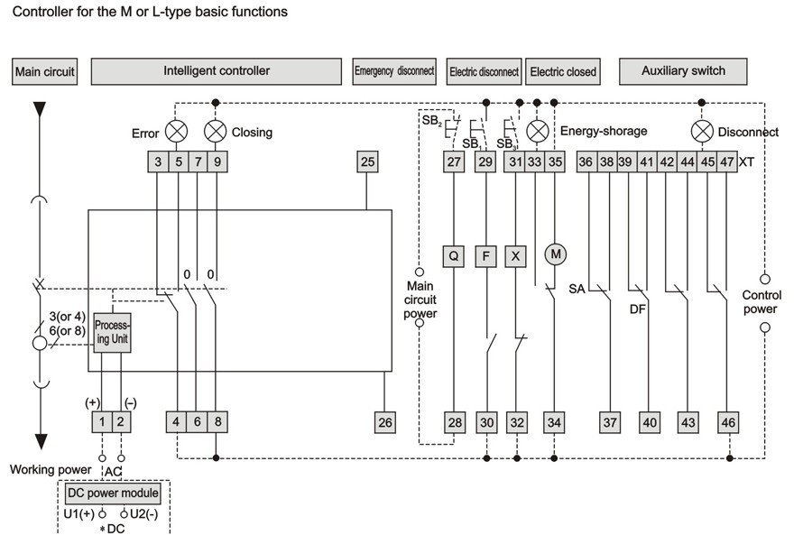
Basics 8 aov elementary block diagram. It opens or closes a circuit automatically or manually.
Air Circuit Breaker Schematic Diagram Manual
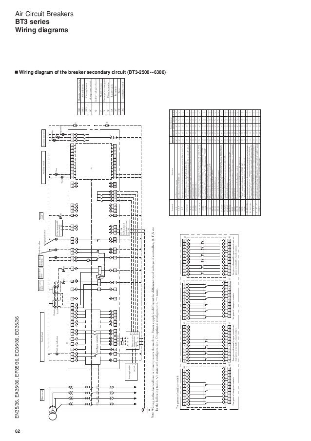
Acb panel wiring diagram. Technical information 3 standard diagrams transfer between 2 sources 1 bus bar comut 041 a load g s1 g s2 p1 p2 standard solution. We can find these systems in distribution panels below 450v. A wiring diagram is a streamlined standard pictorial depiction of an electric circuit. Basics 7 416 kv 3 line diagram. It shows the components of the circuit as simplified shapes and the power as well as signal connections between the devices. Air circuit breaker acb is an electrical device used to provide overcurrent and short circuit protection for electric circuits over 800 amps to 10k amps.
Air circuit breaker function. Air circuit breaker acb air circuit breaker acb is an electrical protection device used for short circuit and overcurrent protection up to 15kv with amperes rating of 800a to 10ka. This is a pretty good amount of power and. Basics 11 mov schematic with block included basics 12 12 208 vac panel diagram. Basics 13 valve limit switch legend. It operates in air where air blast as an arc quenching medium at atmospheric pressure to protect the connected electric circuits.
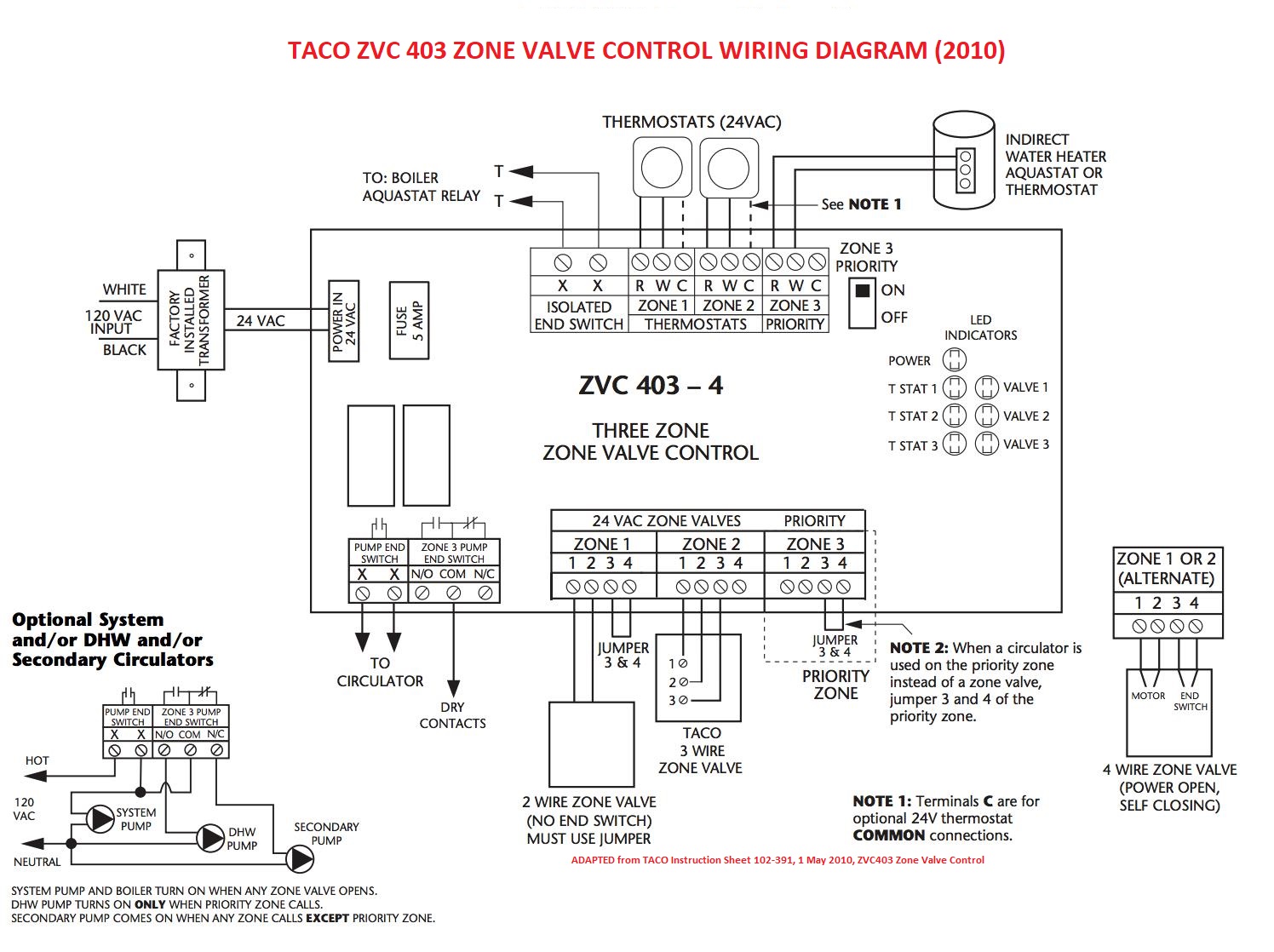
It dampens the arcing in case of overloading. Variety of square d breaker box wiring diagram. Open circuit automatically when a fault take place such as over current short circuit earth fault over frequency reverse power etc. This diagram illustrates some of the most common circuits found in a typical 200 amp circuit breaker service panel box. Basics 14 aov schematic with block included basics 15 wiring or connection. Wiring diagrams sometimes called main or construc tion diagrams show the actual connection points for the wires to the components and terminals of the controller.
They show the relative location of the components. Basics 10 480 v pump schematic. Motorised switch cl ncl g q1 q2 ats automatic transfer switch protection arent shown on the following schemes summary. They can be used as a guide when wiring the controller. Series parallel wiring thirty two panel solar system 2 groups of 16 watts since we connected thirty two panels together in series and parallel this solar system will output 2016w of power per hour maximum under optimal sunlight conditions. Basics 9 416 kv pump schematic.
Functions of air circuit breaker are. Figure 1 is a typical wiring diagram for a three phase mag. Solar panel wiring diagram 9usage and limitations. The breakers are installed in a panel so that contact is made with one of two hot bus bars running down the middle of the box. Breaker contactor or motorised switch socomec diagram. The hot wire for a branch circuit is connected to the breaker by a set screw on the base.
These are usually used in low voltage applications below 450v. Wiring diagram book a1 15 b1 b2 16 18 b3 a2 b1 b3 15 supply voltage 16 18 l m h 2 levels b2 l1 f u 1 460 v f u 2 l2 l3 gnd h1 h3 h2 h4 f u 3 x1a f u 4 f u 5 x2a r.


