Wiring diagrams amerex wiring plan view power source manual reset relay electric gas valve microswitch installer provided junction boxes basic wiring diagram power source manual reset relay red common yellow no black nc gas valve note. All wiring should be done in accordance with the latest edition of the national electrical code ansi nfpa 70 and any local codes that may apply.

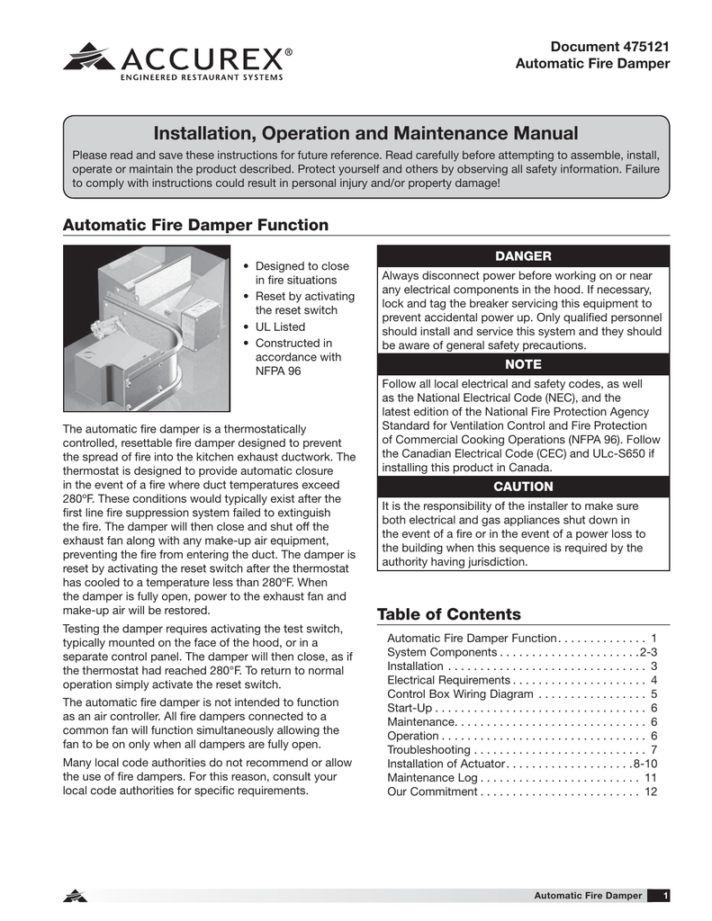
Automatic Fire Damper 475121 Manualzz
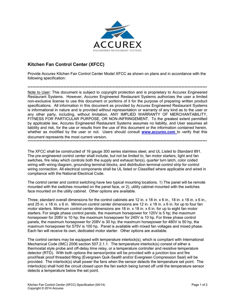
Accurex xfcc wiring diagram. Heritage parts is a trusted distributor of accurex replacement parts. Some are essential to make our site work. Find previous and current installation operation and maintenance manuals for all your accurex products. View online or download accurex xrrs installation operation and maintenance manual. General wiring diagram this is an example of a generic wiring diagram of a xfcc. Accurex recommends using one xfcc per hood system activates all fans simultaneously.
To see your job specific drawing look on the inside panel of the xfcc. This makes controlling your kitchen systems much easier through one stop control. Do not use yellow wire on microswitch in normal microswitch installation. Electrical industry network 15824 views. Accurex xrrs pdf user manuals. Others help us improve the user experience.
Electrical wiring the resturant from hell ses done duration. Accurexs fan control center manages all of the various power connections and relationships between the hoods fans make up air and lighting from a single source. Right part right time every time. The control center and control switching have two typical mounting locations. The xfcc is configured with two exhaust fans and one supply fan as well as three digital interlock sensors. Following wiring diagrams duration.
By using the site you consent to the placement of these cookies. The xfcc is designed for both type i and type ii grease and non grease constant volume hood systems where starters are needed to activate fans. Complete wiring diagrams are attached to the inside of the control center doors. This site uses cookies to store information on your computer. Before connecting power to the unit read and understand the following instructions and wiring diagrams. Wiring with wiring diagram grounding terminal blocks and distribution terminal control strip for control wiring connection.
With same day shipping real time inventory and always 100 genuine oem parts heritage is your one stop destination for commercial kitchen replacement parts. L1 n control input. All electrical components shall be ul listed or classified where applicable and wired in compliance with the national electrical code. 120vac 15amps from breaker g installation location. The control center can operate both single and three phase fans.


