Start up control with io and id run control panel default configuration program features parameters additional parameter data fieldbus control through the embedded fieldbus interface efb fieldbus control through a fieldbus adapter fault tracing and control chain diagrams. This package is also available with an e clipse bypass motor starter with an optional drive service switch f267.

Abb Ach550 01 User Manual Pdf Download Manualslib
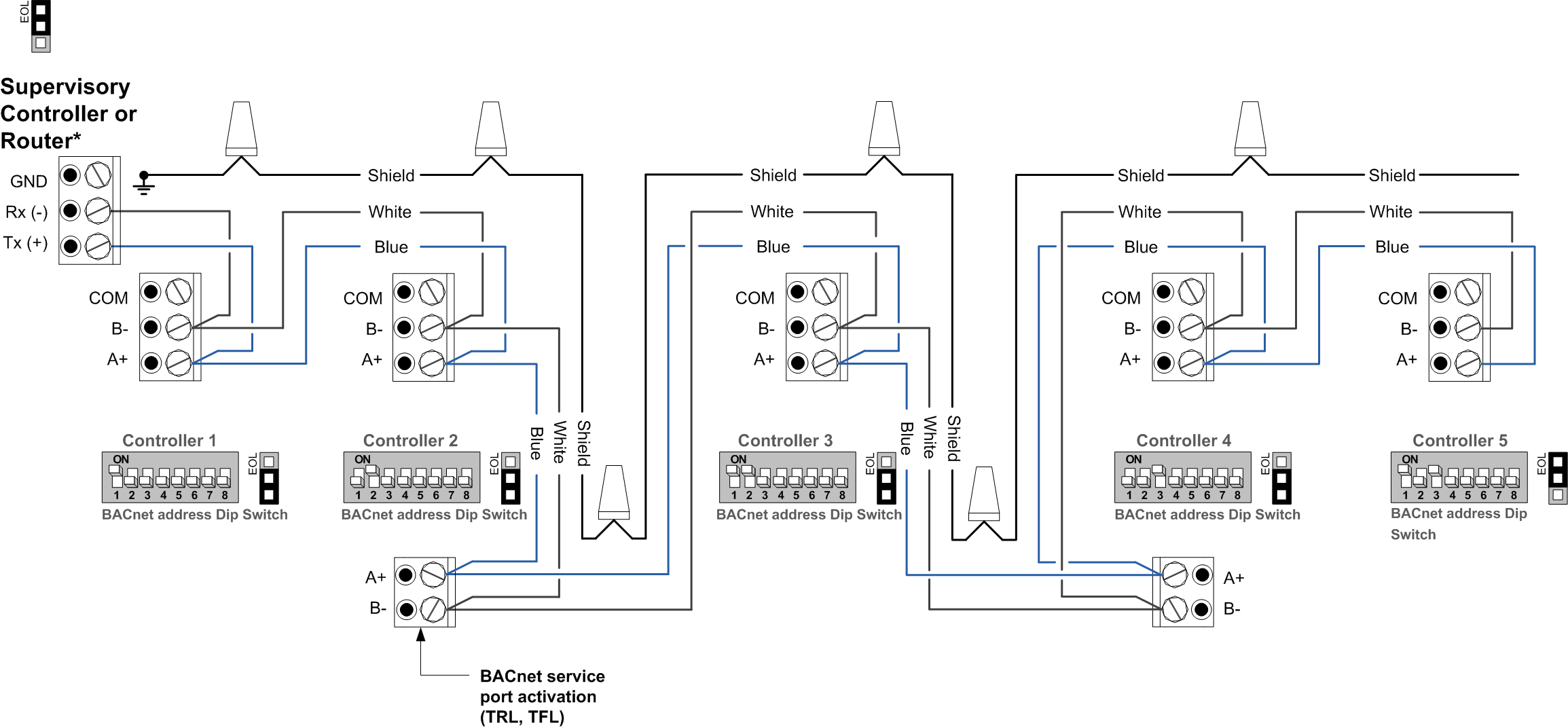
Ach580 wiring diagram. The following figures show the layout and wiring connection points. It also shows a general diagram of power connections and control interfaces. Page 93 ach580 installation operation and maintenance manual connection diagrams box e clipse bypass ach580 box e clipse bypass units are configured for wiring access from the top for ul nema type 1 and 12 and from the bottom for ul nema type 3r. Ach580 01 technical data sheet technical data supply connection voltage and power range 3 phase 380 to 480 v 10 15 075 to 250 kw auto identification of supply voltage frequency 48 to 63 hz fundamental power factor 098 efficiency at rated power 98 motor connection. Operation principle 36 operation principle and hardware description operation principle the ach580 01 is a drive for controlling asynchronous ac induction motors permanent magnet motors and synchronous reluctance motors synrm. Ach580 01 quick installation and start up guide 3aua0000076330.
The following figures show the layout and wiring connection points. Table of contents 1introduction to the manual 2start up control with io and id run 3control panel 4. The ach580 ultra low harmonic ulh packaged drive is an ach580 31 hvac drive enclosed with either an input disconnect switch and fast acting fuses or an input circuit breaker in an ul nema type 1 12 or 3r enclosure. Ach580 hvac control program firmware manual drive composer version for ahvk2208x. The abb ach580 firmware manual contains information on. Settings io and diagnostics on the control panel.
Page 239 ach580 e clipse bypass and packaged drive user manual connection diagrams box packaged drive with input disconnect ach580 packaged drive units are configured for wiring access from the top for ul nema type 1 and 12 and from the bottom for ul nema type 3r. Control chain diagrams page 369 describes the parameter structure within the. Control through a fieldbus adapter control chain diagrams parameters users manual user manual ach580 firmware manual. The reader is expected to know the fundamentals of electricity wiring electrical components and electrical schematic symbols.


