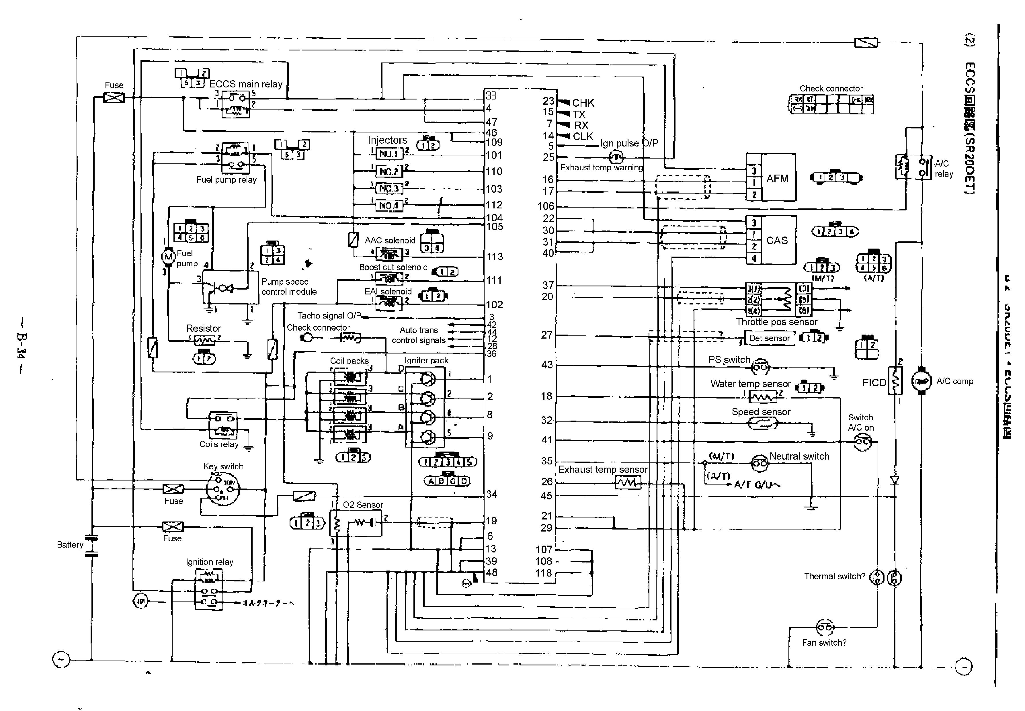
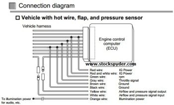
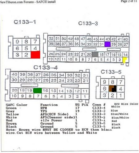
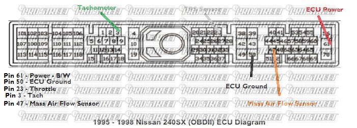
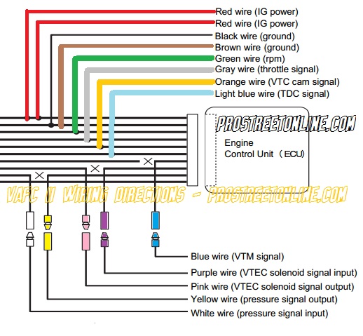
Wiring diagram by model this document describes car models to which the afc neo product code. 5connect the harness attached to the safc ii to the plug installed in step 4 6insulate the splice and unused plug with electrical tape.

Afc Printable
Afc 5 button wiring diagram. Apexi safcii 2 ecu wiring diagrams english. Apexi super itc 5 button knob old school instruction manual ecu wiring. Exhaust system manuals center pipe 144 n052 downpipes 145 m005 gt spec 172 kt05 172 kh14 172 kh13. Bertemu kembali dengan entri pemasangan serta wiring yang perlu dilakukan untuk memasang apexi super afc atau lebih dikenali sebagai 5 button dalam kalangan peminat dunia automotive. Connection diagram for s afc and other equipment 81 nissan 82 toyota 83 mitsubishi 84 honda 85 mazda 86 subaru 87 isuzu 88 suzuki 89 daihatsu. Troubleshooting for the 5 button 3109228001 comfort control center system a.
Apexi product manuals find product manuals wiring diagrams other useful information for the apexi product catalog. Apexi rsm rev speed meter round button wiring instructions. 3wiring diagram by model 4collection of setting data super airflow. Apexi super afc 5 button knob old school instruction manual ecu wiring. 401 a917 is applicable and ecu terminal arrangement drawings. Reversing v alve tools required the air conditioner can be checked with a voltmeter ohm meter clamp on ammeters and two good thermometers.
7reconnect the negative ー terminal of the battery. Atas permintaan beberapa orang followers blog ini yang meminta saya memuatkan entri berkaitan pemasagan engine management jenis ini maka saya tunaikan permintaan mereka lagipun tidak ada lagi entri mengenai 5. For the operating method and precautions for the afc neo refer to the instruction manual. Apexi safcii 2 ecu wiring diagrams japanese. Ac power module 17. Switch with a center pushbutton and a rotary switch gets rid of the button to button distance and permits quick operations thereby providing efficient operation of the unit.
In the panel there are sufficient knock outs located around the periphery of the cabinet to allow the installer to. Please be careful not to make improper connections or short out the unit. The following diagrams view the coupler from the same angle as the diagram. Some clamp on ammeters can read voltage and ohms. Be maintained by at least 025 inches and the wire insulation must be for the higher voltage. Dc v olt age 9.
4cut the airflow signal wire or pressure signal wire of the vehicle harness and install a plug by referring to the vehicle specific wiring diagram. The super afc ii is a fuel adjustment controller in which the airflow sensor signal or the p.
