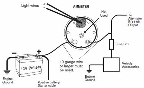
Once you have connected it to the ammeter you will then connect it to the alternator terminal. Under normal conditions the meter should show a small charge.

Ammeter Classicoldsmobile Com
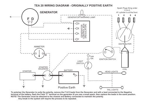
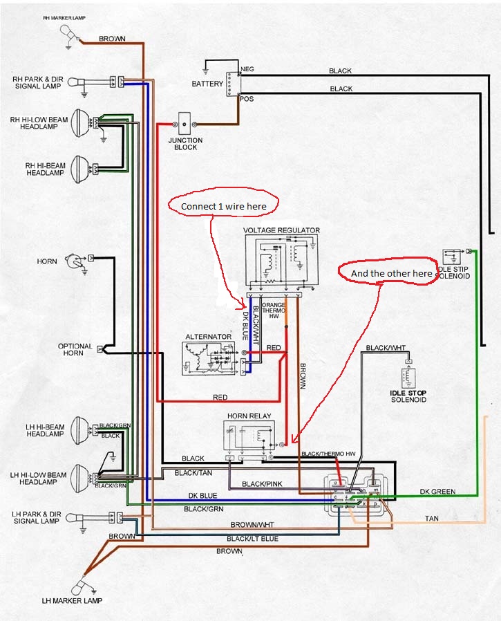
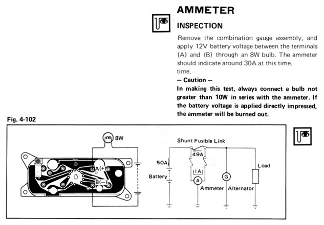
Ammeter wiring diagram. With your positive battery terminal now connected to the ammeter you are ready to connect the next wire. The ammeter shows direction and rate of current to and from the battery. Lamp socket push in wedge type 1 3. Wiring for ammeter or voltmeter. A short description of how to wire in an ammeter or voltmeter for your car from someone who understands the principles. Step 4 connect the ammeter to the alternator.
Installation instructions 1 ˇ ˆ. The primary purpose of an ammeter is to indicate the charging rate of the generating system and to check on the current of the boats lights accessory and ignition equipment. The following circuit represents the basic circuit diagram and the connection of the ammeter circuit in series and parallel are shown below. Amp gauge wiring 1 always disconnect the ground lead from the vehicle battery before wiring any gauge. Light bulb 12 volt ge. 2 classic instruments amp gauge should only be used on vehicles with alternators rated at 60 amps or less.
Most boats make provisions in their wiring for adding in. Read these instructions thoroughly before making installation. It reveals the elements of the circuit as simplified forms and the power and signal connections between the devices. Vdo mounting bracket and nuts 2 1 5. Refer to the boat and engine manuals for details of the wiring system and ammeter installation wiring diagrams. Ammeter 2¹₁₆ 52 mm diameter 1 2.
Ammeter circuit diagram the construction of ammeter can be done in two ways like series and shunt. Wire minimum with an insulation temperature rating of 220 f 105 c minimum from the battery terminal on the starter solenoid to the right terminal on the ammeter see wiring diagram. The voltmeter ammeter can be easlily calibrated by temporaily connecting three setup up down tactile buttons or even a piece of wire to c1 c2 and c3 pic16f876 microcontroller ports. Assortment of volt amp meter wiring diagram. A wiring diagram is a simplified traditional photographic representation of an electric circuit. This will be higher after starting but probably never.
To enter the calibration setup mode make sure the meter is powered off. Using an alternator with higher output capacity is dangerous and could cause a fire. Brian questioned the accuracy of the diagram indicating he followed the diagram. Take your other piece of red 14 gauge wire and connect it to the other terminal of the ammeter. Ferguson to 20 wiring and ammeter installation at a recent meeting of fena members in wakarusa in brian schultz of hamlet in raised a question about the wiring diagram for the to 20 with indicator light on our web site. 158 or equivalent 1 4.
Do not deviate from assembly or.


