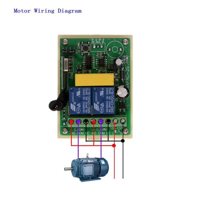
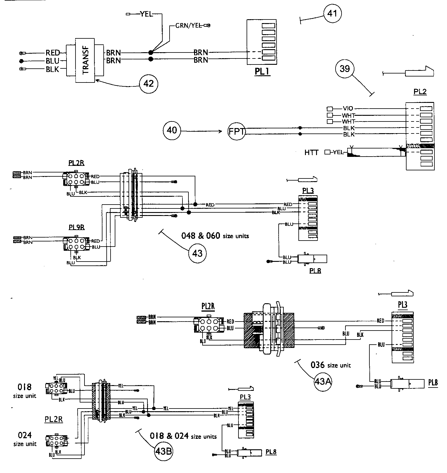
Installation start up and service instructions manual. A wiring diagram is a simplified traditional pictorial depiction of an electric circuit.

The Lockout Relay Circuit
Apac wiring diagram. Installation operation and maintenance manual. Wiring diagrams index unit 50byn v ph hz label diagram fig. Number 006 024 winter start 4 evaporator defrost thermostat 5 temp. We ei only se sis y1w1 i is reee to se sw to e off sii sw. It shows the components of the circuit as simplified shapes and the power and signal connections between the devices. Single stage cooling and heating.
Dimensions and wiring diagrams example 2. Phase 3 can aid you in understanding the colour coding standards for equipment wiring as well as housinginstallation wiring. Moreover the heat source for a basic ac system can include heat strips for electric heat or even a hot water coil inside the. Number 006 008 208230 3 60 460 3 60 11720011 c 1 575 3 60 012 208230 3 60 014 460 3 60 11720960 b 2 016 575 3 60 024 208230 3 60 460 3 60 1172007 c 3 575 3 60 accessory wiring unit 50byn accessory description fig. We eier y r w is e ee i is reee to se sw to e off sii example 3. Wiring colours in australia have changed a few times in the history of consumer electrical equipment and this article hopes to clear up some of the mystery.
Installation start up and service instructions manual. Single stage cooling and heating with dedicated fan speed relays ne. How to wire an air conditioner for control 5 wires the diagram below includes the typical control wiring for a conventional central air conditioning systemfurthermore it includes a thermostat a condenser and an air handler with a heat source. Single stage cooling and heating ne. Collection of central air conditioner wiring diagram. Smart temp australia are a progressive supplier of quality heating and air conditioning controls apac.
Installation and start up instructions manual.


