Real time data can be fetched using our internet based scada system. Psif we can get to 200 likes i will make another.

Wiring Diagram Xbox 360 Power Supply Image Collections
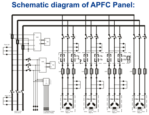
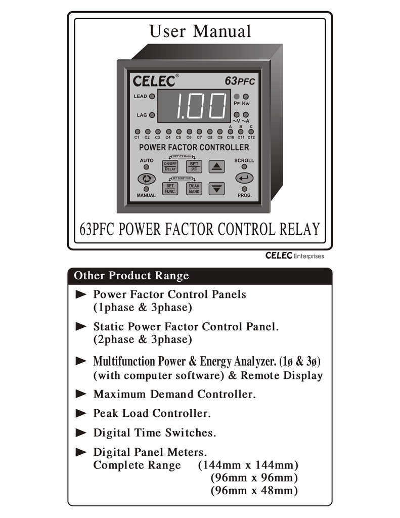
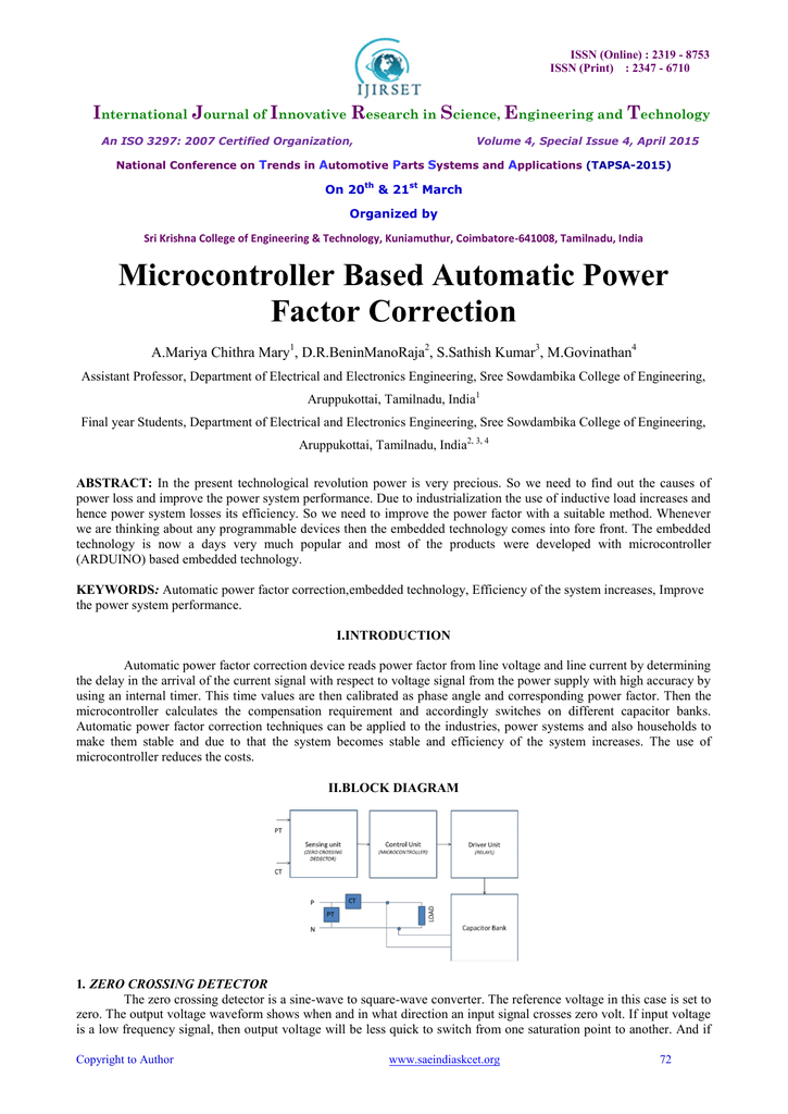
Apfc relay control wiring diagram. Power factor relay settings and programme electic gyan centre. This gprsgsm based logical controller and web based scada system cut the maintenance costs and increases the devices uptime. That photograph apfc relay control wiring diagram apfc panel wiring diagram pdf within relay panel. Apfc relay automatic power factor controller relay. Therefore monitoring and control can be done from any location. Suggested electric fan wiring diagrams page 1.
Thanks go to bob wilson volvodad on brickboard for contributing to these differences. 4 safety precaution use the device correctly after reading the following explanation before use. In this publication the line diagrams show the control circuits only power circuits are omitted for clarity since they can be traced readily on the wiring diagrams heavy lines. Check out the circuit diagram apfc control circuit diagram. In this video you will see how to wire power factor relay and power capacitors to create a complete power factor correction panel. Pfcs measure voltage and current calculates the reactive and active power and switches capacitors depending on the reactive power that needs to be corrected.
Be sure to follow instructions in order to use the device safely. A wiring diagram gives the necessary information for actually wiring up a group of control devices or for. Apfc panel f2 h1 f1 1 m c 1 m k 1 m sdf cr t tr power transformer u rent a sfo m p ow erfa c tn l switch disconnector fuse contactors capacitor stop fuses control fuses capacitor stops safe sure 63 lt switchgear e s p s e r v i c e m a n u a l. Through the thousands of pictures on the web about relay panel wiring diagram we choices the top libraries using best quality simply for you all and now this images is actually one of images choices in your best photos gallery regarding relay panel wiring diagrami really hope you may want it. Apfcs have 6 to 16 relay steps for capacitor bank switching. Interface measurement and control relays measurement and instrumentation motion control and robotics motor starters and protection components plc pac and dedicated controllers power supplies power protection and transformers process control and safety pushbuttons switches pilot lights and joysticks sensors and rfid system.
Apfc panel wiring diagram capacitor calculations. This type of relay will work for this application also but you will not use pin 87a. In a changeover relay the 87a pin will be hot anytime the 87 pin is off so long as power is connected to pin 30. 15 apfc panel for automatic control of pf pfc.
