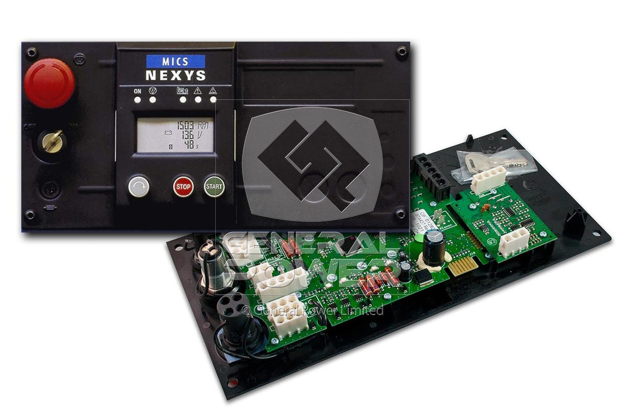
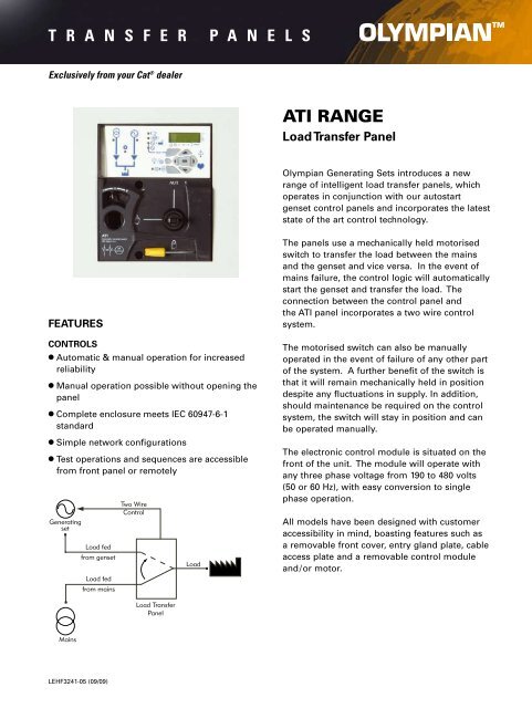
The apm 303 is a instrumentation and control system for generating sets. Basics 9 416 kv pump schematic.

Pdf Chapter 15 Construction Of A Paleozoic Mesozoic
Apm303 wiring diagram pdf. Wiring diagram book a1 15 b1 b2 16 18 b3 a2 b1 b3 15 supply voltage 16 18 l m h 2 levels b2 l1 f u 1 460 v f u 2 l2 l3 gnd h1 h3 h2 h4 f u 3 x1a f u 4 f u 5 x2a r power on optional x1 x2115 v 230 v h1 h3 h2 h4 optional connection electrostatically shielded transformer f u 6 off on m l1 l2 1 2 stop ol m start 3 start start fiber optic. Basics 7 416 kv 3 line diagram. Basics 10 480 v pump schematic. Basics 8 aov elementary block diagram. Basics 11 mov schematic with block included basics 12 12 208 vac panel diagram. Application diagram for situation no.
Single coils humbuckers humsingsing humsinghum and much more. Search by pickup type clear all. Guitar wiring diagrams for tons of different setups. 1923 chevrolet car wiring 1923 chevrolet general wiring 1923 chevrolet superior model 1923 chevrolet wiring 1925 chevrolet superior model series k 1927 chevrolet capitol and national 1927 chevrolet capitol and national models 1928 chevrolet general wiring 1928 chevrolet wiring 1928 chevrolet. Chevrolet vehicles diagrams schematics and service manuals download for free. Sdmo apm303 digital control panel pn 31613629300.
This means that a user can modify all the internal parameters no access code in the apm303. Click here to learn how to install your pickups. Refined search clear all. View online or download sdmo apm303 user manual. 12 integrating the apm303 in its environment the apm303 is integrated into central console equipment type s1500 s2500 s3500 s4500 fitted on the base frame of the generating set on versions ii and iv enclosure. 2 option details installation powered on automatically controlled normalemergency switching unit emergency generating set automatic starting order up to 2 confi gurable.
Basics 14 aov schematic with block included basics 15 wiring or connection. It can be found in the sdmo range for generating sets under 300 kva. Identification of the modules 01 switch located on the front of the central console. Montick is supplied with a wiring harness outputs connected on the top connector as indicated below and inputs connected on the bottom connector. Figure 1 integration of the apm303. On powering up the apm303 automatically runs in the operating mode which was pre set before it was switched on see section selecting the operating mode.
The wiring diagram for the equipment provided with this manual before powering on. 12v and 24v operation no ecu communication options available modbus function configurable via pc and screen auto man modes. For the apm303 sdmo controller we supply quick splice connectors figure 2 so that the montick harness can be connected to the apm303 harness without unscrewing connector blocks. Plus info on switches pots coil splitting and more. Basics 13 valve limit switch legend. Sdmo apm303 pdf user manuals.
Datasheet apm303 february 2014 to facilitate the transition between the nexys and the apm303 sdmo offers an apm303 kit to replace a nexys.


