Figure 5 wiring diagram gray code altitude input apollo sl70 installation manual. Transponder is suppressed when input is high.

Apollo Marine Entertainment System With Built In Wi Fi
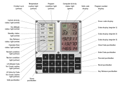
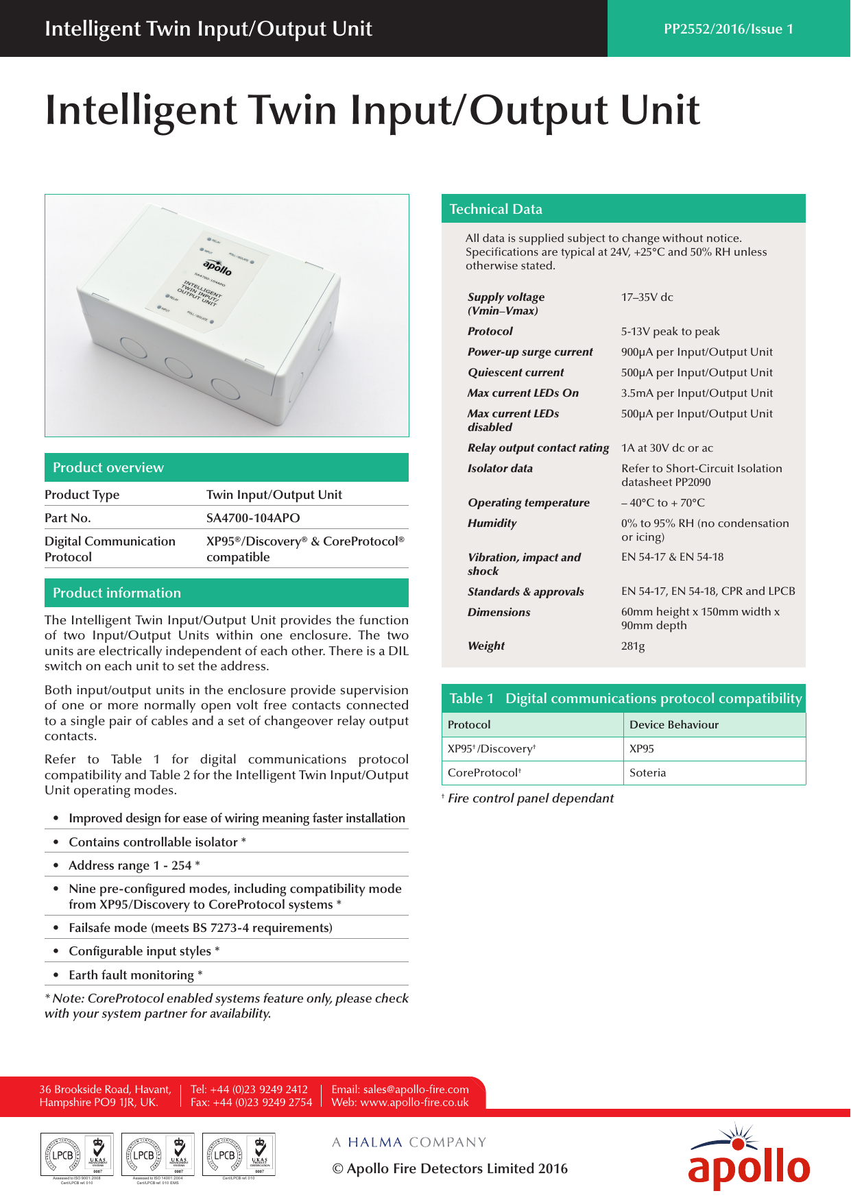
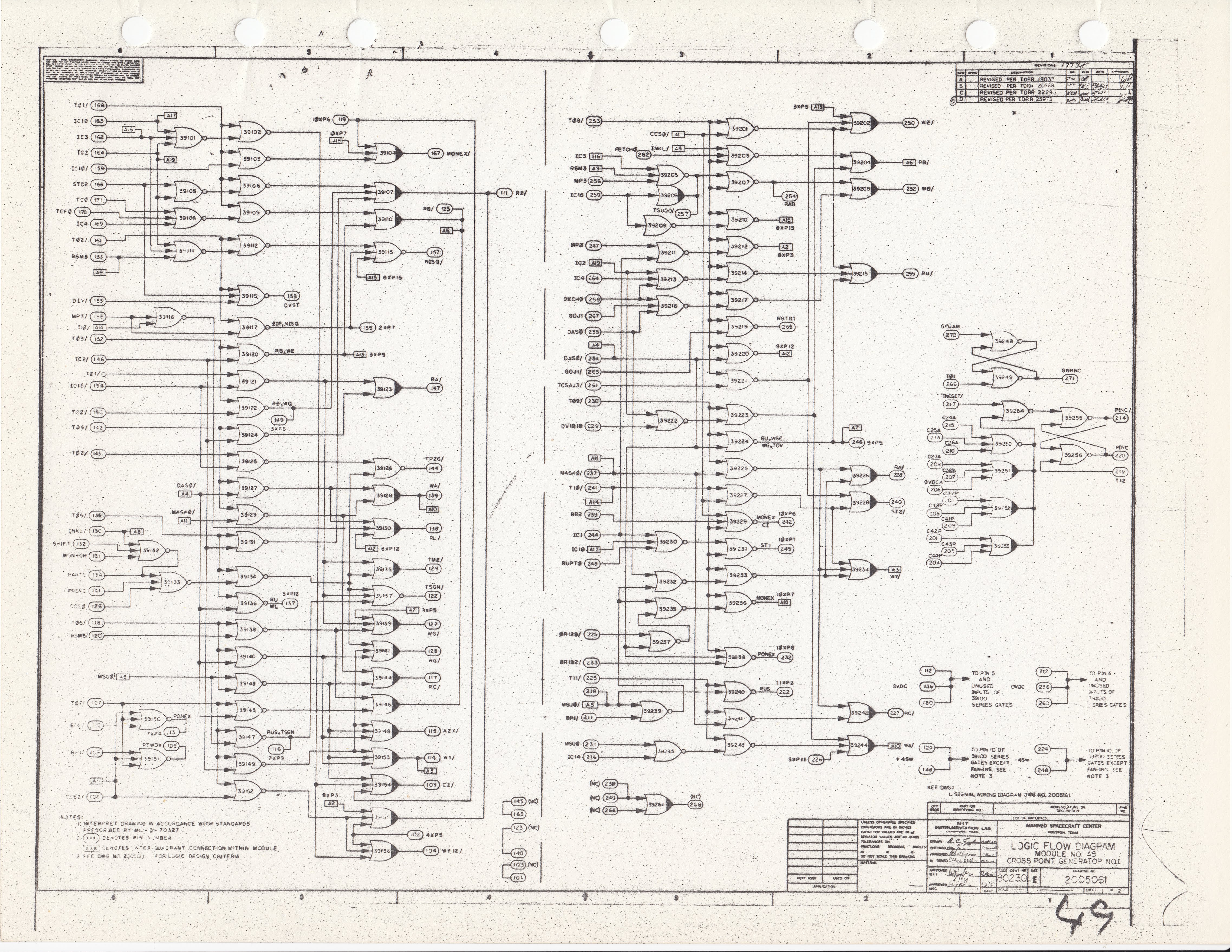
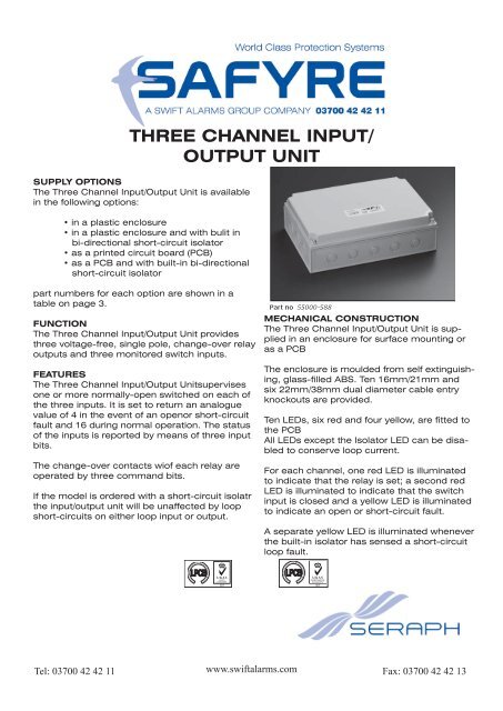
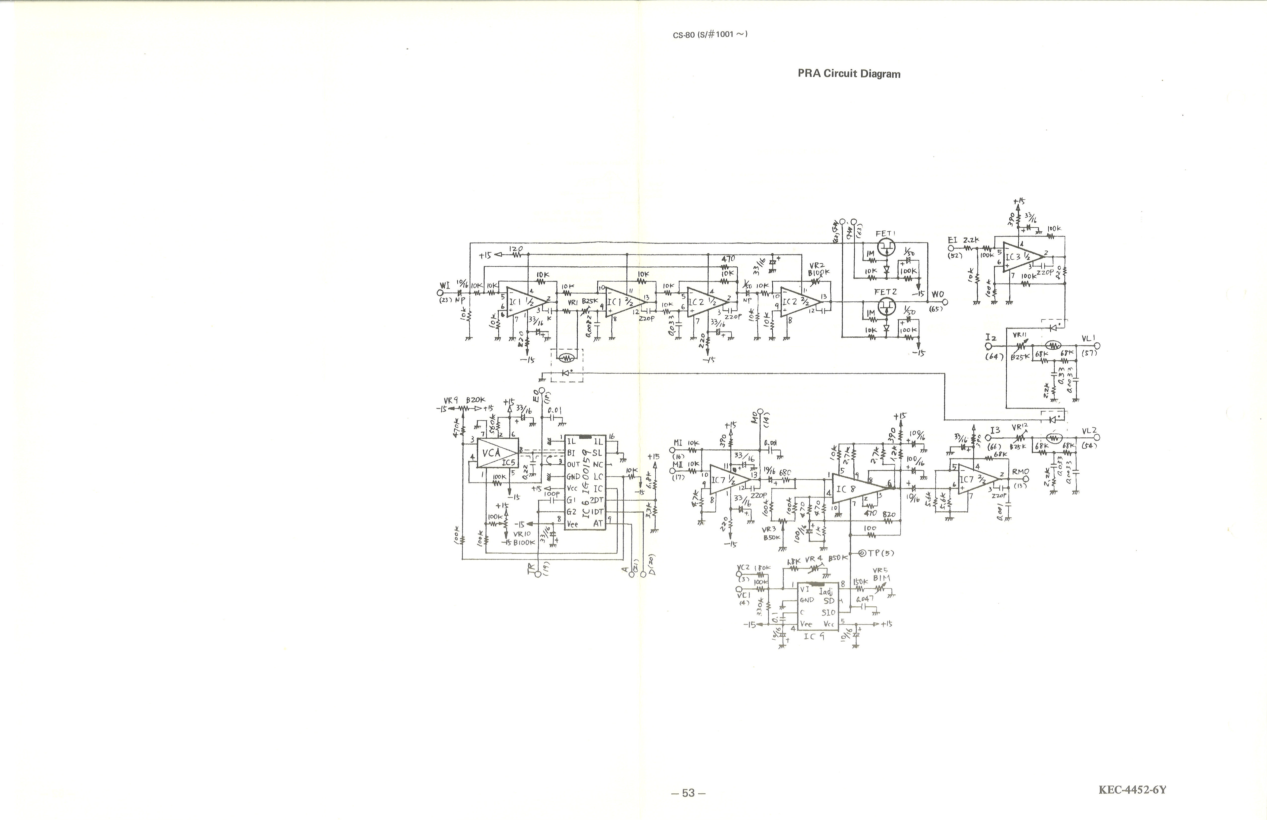
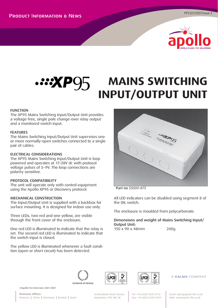
Apollo input output unit wiring diagram. The intelligent inputoutput unit provides supervision of one or more normally open contacts connected to a single pair of cables and a set of changeover relay output contacts. Suppression input typically connected to dme suppression output. Figure 6 wiring diagram serial altitude input 2. Memory mapped low core addresses. Rs232 serial data input rs232 signal ground intercom function select pulled low to turn on the intercom function speaker and headphone ground connection headphone terminal output microphone input 2 viewed from rear of unit apollo sl40 installation manual. The apollo guidance computer.
A copy of the declaration of performance is available from apollo on request. Consoles routing is so flexible that just about any console channel can be fed by whatever hardware input you want. Customizing io settings in consoles matrix is great if youre using more than one apollo need to connect an adat device or even if you just want to rearrange the order of your channels. Io channels mapped as memory addresses in low core accessible only by io instructions all 16 bits wide 7 input channels 14 output channels most are single bit status flags. If using an external device with an optical spdif output such as a gaming console home stereo receiver cable box etc use a standard optical cable toslink to connect from the spdif output of the external device to the optical input on the apollo twin apollo twin mkii or apollo 8p. Customize console input channels.
Improved design for ease of wiring meaning faster. Unit is in standby when input switched to ground.


