This website uses cookies. Transformers belimo actuators require a 24 vac class 2 transformer.

Https Www Unescaped Me Post Thermistor Wiring Diagram
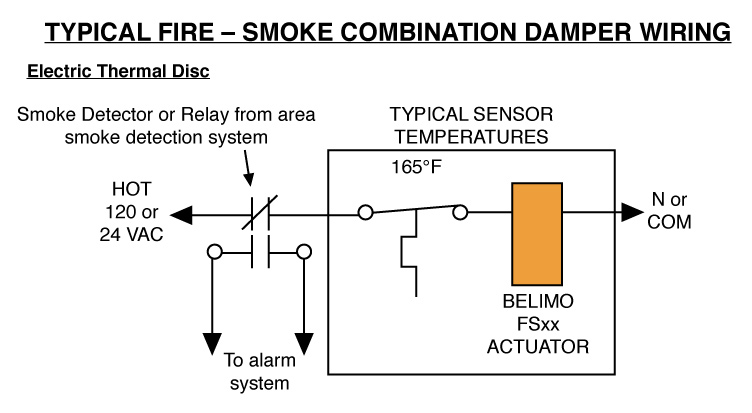
Belimo tfb120 s day wiring diagram. It shows the parts of the circuit as streamlined forms as well as the power and signal links in between the gadgets. Actuators input and output wiring with suitable flexible conduit. Follow all instructions in this literature. Belimo automation ag 25775 views. Actuators shall be as manufactured by belimo. Actuators may be connected in parallel.
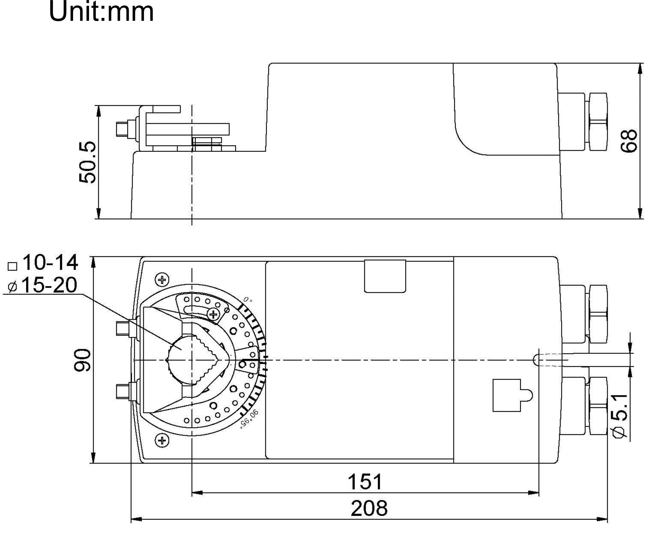
During installation testing servicing and troubleshooting of this. If you have any questions contact the controller manufacturer andor belimo. Dimensions inchesmm 077 196 039 99 45 114 02 51 628 1595 30 762 33 838 240 61 068 173 33 838 tfb120 s damper actuator technical data sheet onoff spring return ac. Belimo tfb120 s wiring diagram gallery collection of belimo tfb120 s wiring diagram. The tf24 3 s us and tf24 sr s us actuators rotate clockwise when the switch is in the cw position and power is applied to wire 3. Rotating the direction of rotation switch to ccw reverses the control logic.
Power consumption must be observed. 4 for end position indication interlock control fan startup etc tf120 s us. A wiring diagram is a streamlined conventional pictorial depiction of an electrical circuit. Actuators shall be as manufactured by belimo. Detailed information about the use of cookies on this website is available by clicking here. Damper actuator 22 in lb 25 nm spring return ac 100240 v onoff 1 x spdt.
By using and further navigating this website you accept this. When power is applied to wire 4 the actuator rotates counter clockwise. Tfb120 technical data sheet onoff spring return ac 100240 v 800 543 9038 usa 866 805 7089 canada 203 791 8396 latin america caribbean. It reveals the elements of the circuit as simplified forms as well as the power and also signal links in between the devices. Variety of belimo tfb120 s wiring diagram. Belimo safety solutions fire protection scenarios duration.
Wiring diagrams 1 provide overload protection and disconnect as required. Building a 35kwh diy solar generator for 650 start to finish duration. A wiring diagram is a streamlined conventional photographic depiction of an electric circuit. 2 caution equipment damage. Properly terminate the conduit in a suitable junction box. Always read the controller manufacturers installation literature carefully before making any connections.


