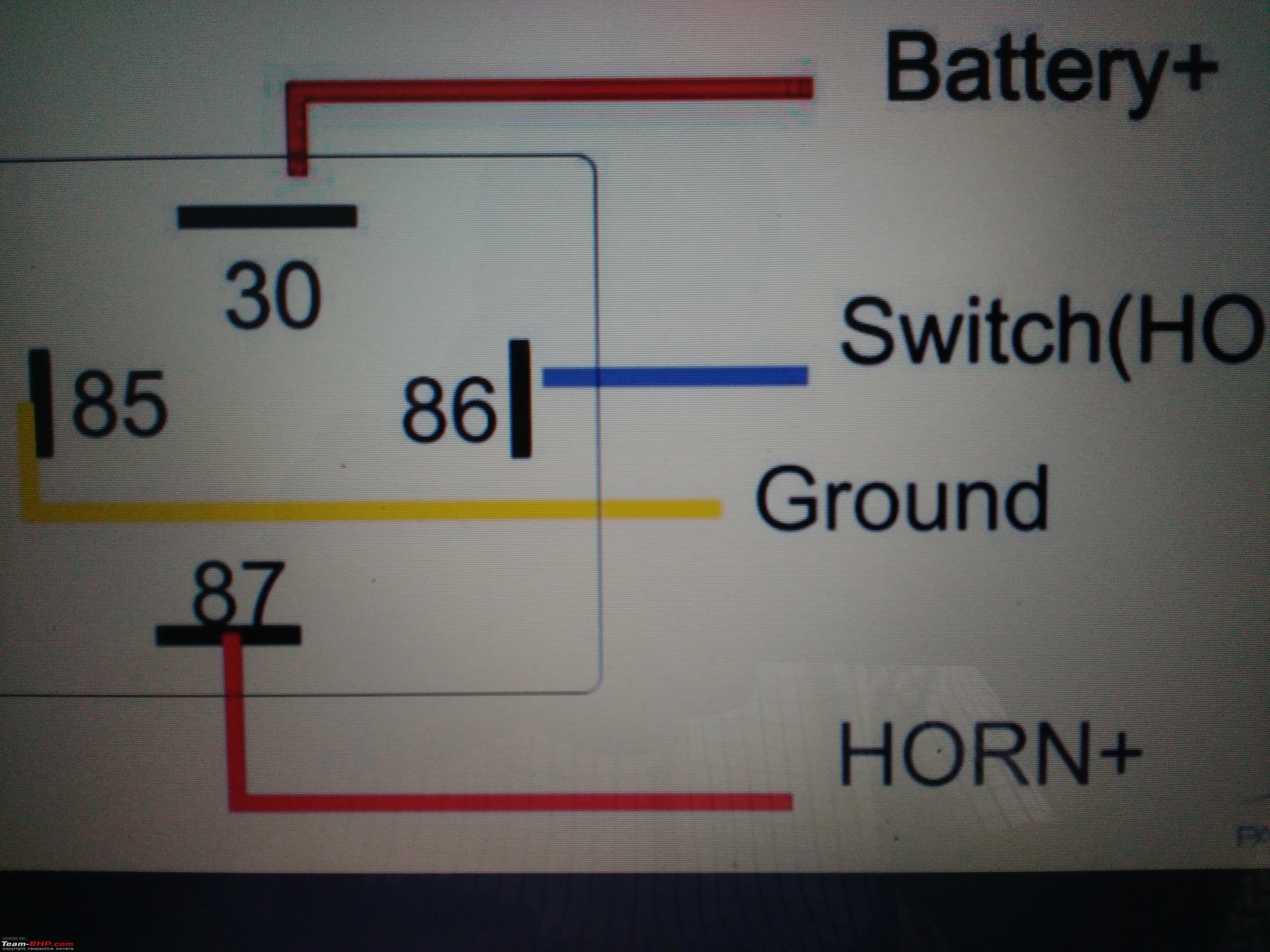
The oscillators output at pin 3 drives the gate of q1. Dual horn installation using horn relay horn relay wiring this is the simplest way to connect two heavy in horns in a bike or a scooter using horn relay.

How To Attach Install Connect Wired Dual Horn Relay Cutout To Bike Car
Bike horn cutout wiring diagram. Electronic bike horn circuit diagram. 17 suzuki motorcycle wiring diagram motorcycle diagram in 2020. Honda anf125 wave 125 electrical wiring harness diagram schematic here. Yamaha ct3 175 electrical wiring diagram schematic 1973 here. Honda c50m c 50 electrical wiring harness diagram schematic here. Potentiometer r1 can be adjusted to set the horns output frequency.
Wiring an electric scooter bike or go kart is as simple as it looks in the drawing. Honda motorcycle electrical wiring diagram schematics. Yamaha ct1 175 electrical wiring diagram schematic 1969 1970 1971 here. Some horn speakers are frequency sensitive so play with the oscillators frequency control for the best loudest sound. Using relaycut out your battery will. Like many bikes of its era keiths gl has dual horns one high toned and one low.
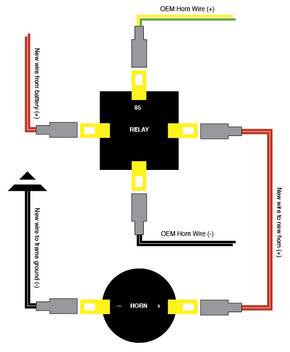
Yamaha at1 125 electrical wiring diagram schematic 1969 1970 1971 here. The diagram above shows the wiring for the new horns. Yamaha at3 125 electrical wiring diagram schematic 1973 here. Color laminated wiring schematics and diagrams for restoring and maintaining classic amc american motors buick cadillac chevy chrysler dodge ford griffith jaguar mercury oldsmobile opel plymouth pontiac studebaker triumph volvo cars and trucks. Here is a basic wiring schematic for an electric scooter bike or go kart which indicates how to hook up all of the components. If you are trying to build a stripped down bike there is a lot going on that you dont need.
Horn upgrade hydraulic clutch jc whitney trunk maier woods pro mirror mount repair oil screen cleaning wiring diagram by bob. Yamaha ct2 175 electrical wiring diagram schematic 1972 here. Honda c70 cub electrical harness wiring diagram schematic. The drain of that fet drives a small horn speaker. The speed controllers wiring directions will precisely indicate which wires to connect to which parts and components. Yamaha at2 125 electrical wiring diagram schematic 1972 here.
Wiring of 3 pin cutout relay is explained in urduhindi completely there are 3 wires in cutout relay 1red wire 2black wire 3white wire 2. Honda c65 cub electrical harness wiring diagram schematic 1964 1970 here. Lots of 70s and 80s bikes will look the same especially the four cylinders. Honda c50 super cub electrical wiring harness diagram schematic here. Install 3 pinwire horn relay switch in bikecar diy. You might have checked the wiring diagram for your bike already and seen something like this.
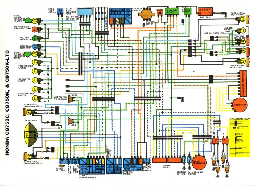
Wiring diagram by bob. For the sake of clarity and comparison the diagram above shows the way the wiring is set up for the stock horn. The above diagram is from a honda cb750 custom dual cam bike. This short how to was inspired when one of the horns on q a man keith fellensteins 1980 honda gl1100 decided itd worked long enough leaving him with a single horn emitting a low decibel barely audible beep.


