Hall effect sensor logic switch output and winding status timing diagram for three phase bldc motor driven anti clockwise. Bldc motor controller wiring diagram collections of sensored brushless dc bldc motor control with pic16f877a.

24v 36v 48v 250w 350w Brushless 6 Mosfet Hub Motor Controller
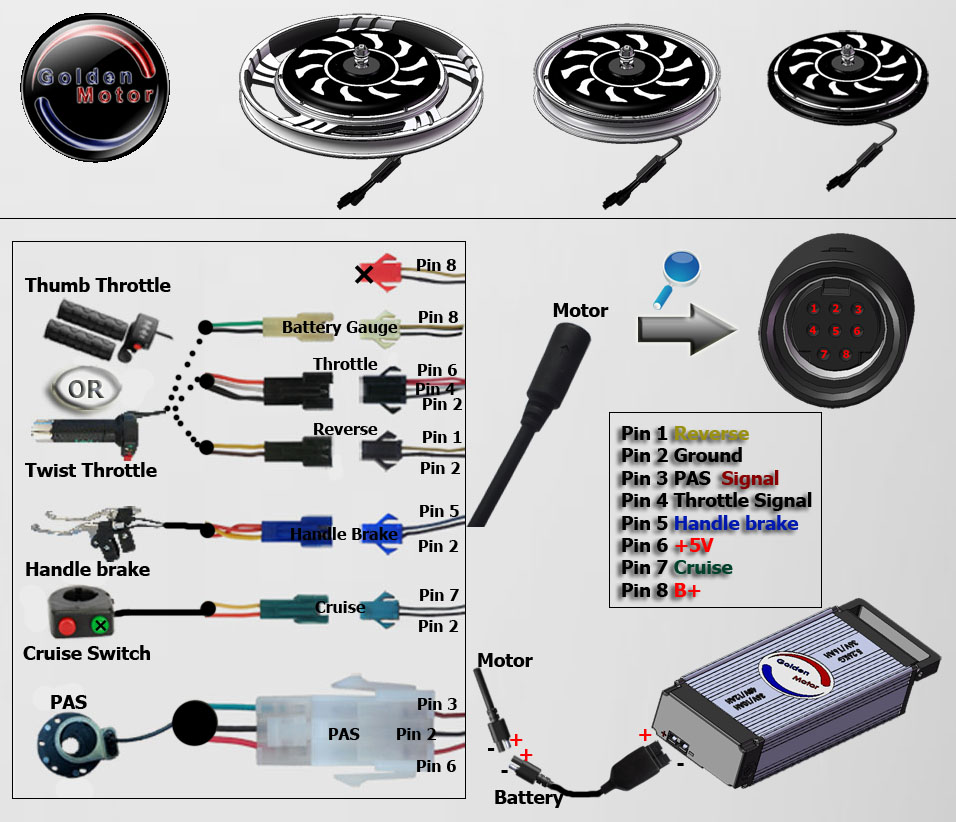
Brushless hub motor wiring diagram. 2018 24v36v48v 250w350w bldc motor speed controller 6 mosfet dual. Esc brushless motor wiring. The problem is how to determine which wire goes where without blowing anything up. A quick and simple designers guide to explaining the benefits of brushless dc motors as well as how to. Hub motor controller aliexpress url. Wiring diagram as well motor controller wiring diagram brushless.
Bldc motor controller wiring diagram. Jalur kabel kontroler 24v 350w cara pasang wiring diagram controller skuter elektrik duration. Some motors may also have a temperature sensor or shaft speed encoder more wires. Electric bike controller wiring diagram in addition electric motor wire connectors additionally electric bicycle controller razor together with bafang electric motor also electric scooter hub motor kit. Most brushless motors used on bikes scooter and motorcycles have 3 phase wires the fat ones that take the power and 5 hall sensor wires the skinny ones. On electric bicycle controller diagram find this pin and more on scooters by nathan shinder.
Reducing its cost as well as eliminating the additional wiring and connections to the motor that would.


.png)


