Obtaining from factor a to aim b. Transformer wiring diagrams three phase buck boost transformer.

Title Buck Boost Transformer By Neeraj S Abhyankar Seminar
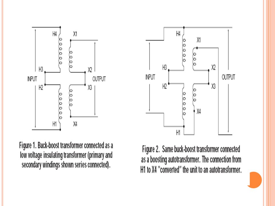
Buck boost wiring diagram. The function is the exact same. Buck boost transformer 208 to 230 wiring diagram collection square d transformer wiring diagram control transformer wiring. Model a 120x240v 1224v model b 120x240v 1632v model c 240x480v 2448v. Single phase only 1x 120 x 240 2x 240 x 480 27 277 lh materialtemperature rise aluminum unshielded aluminum shielded copper shielded copper unshielded 150 c lh sh ch gh 115 c lf sf cf gf 80 c lb sb cb gb 2y secondary. K single phase buck boost 48 primary single or three phase 20 208 24 240 48 480 60 600 three phase primary windings will be delta connected. November 10 2018 by larry a.
Wellborn collection of 3 phase buck boost transformer wiring diagram. Hv higher voltage lv lower voltage when bucking and boosting. Buck boost transformer 208 to 240 wiring diagram a novice s overview to circuit diagrams an initial appearance at a circuit layout could be complex but if you can read a metro map you could read schematics. A buck boost transformer is an insulating transformer with either a 120 v x 240 v primary with. Transformer wiring diagram single phase. It shows the elements of the circuit as simplified forms and also the power and also signal connections between the tools.
A flourescent lighting load requires 18 a per phase with a 480y277 v supply. A wiring diagram is a streamlined conventional photographic representation of an electric circuit. Assortment of buck and boost transformer wiring diagram. The available voltage measures only 436 v phase to phase. The wiring diagram for this application is number 1. Wiring diagrams 208 circuits wiring auto wiring diagrams instructions.
If you are using this unit as an auto transformer to buck lower or boost raise the voltage by a 12 to 48 volts use the information below to select the proper wiring diagram. It shows the components of the circuit as streamlined shapes as well as the power as well as signal connections in between the devices. A wiring diagram is a streamlined traditional pictorial representation of an electrical circuit. Literally a circuit is the course that enables power to flow.


