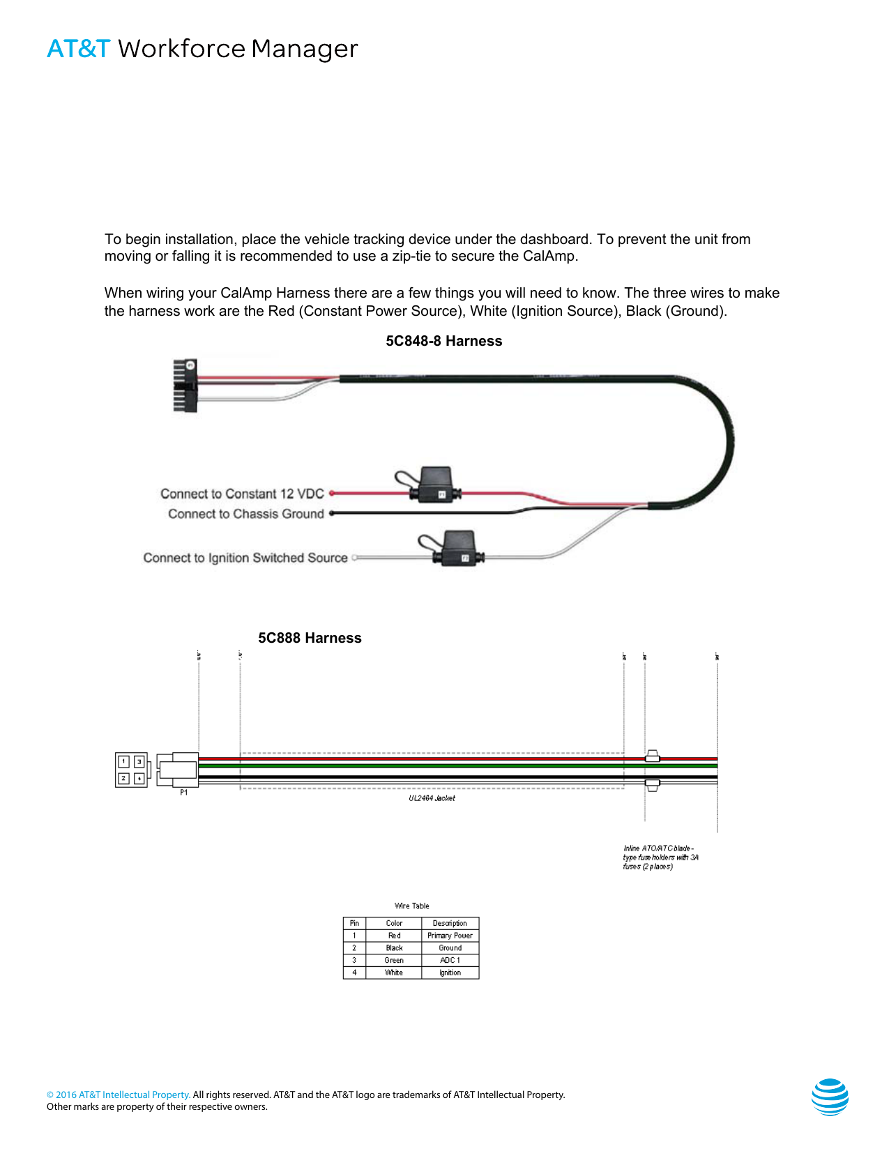
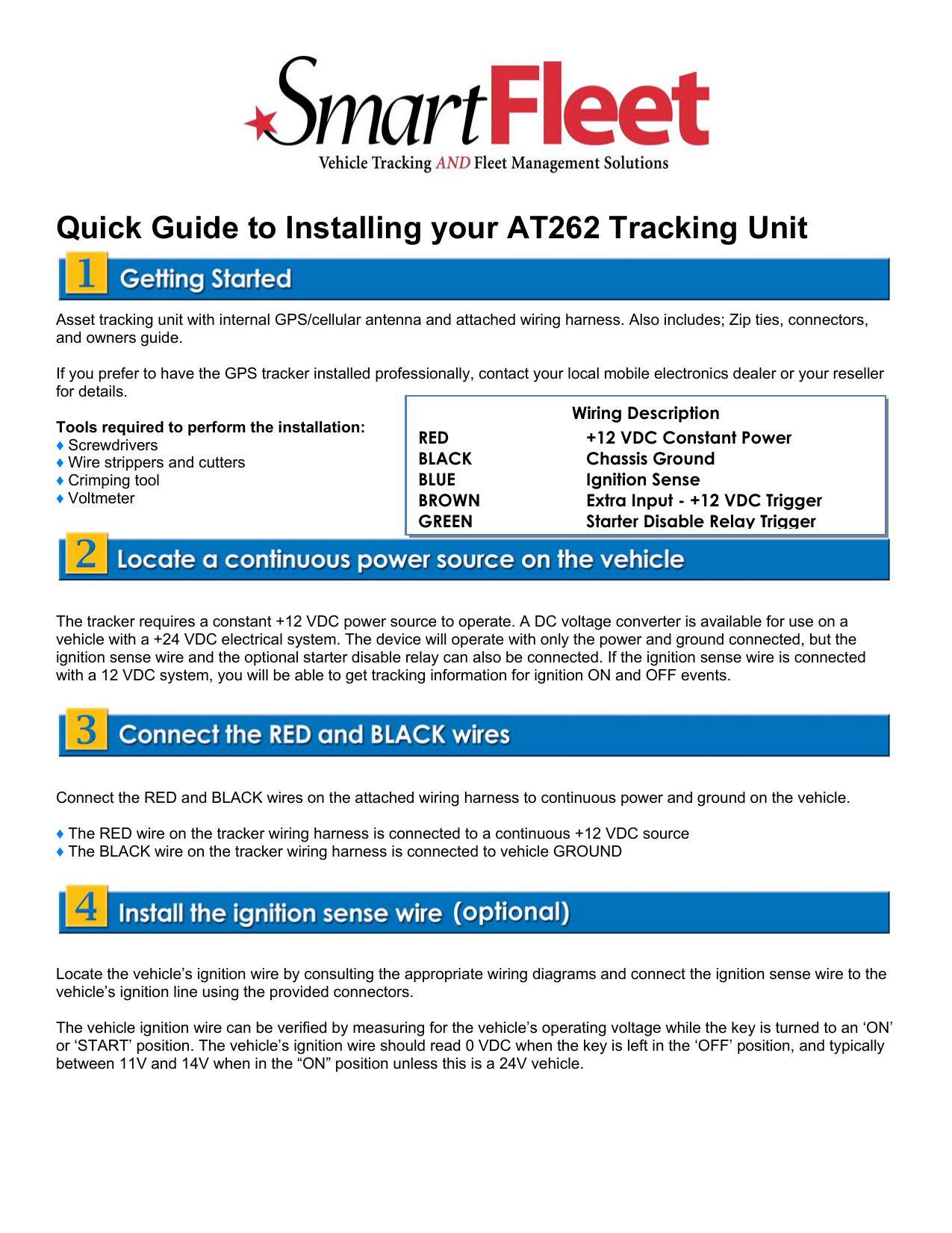
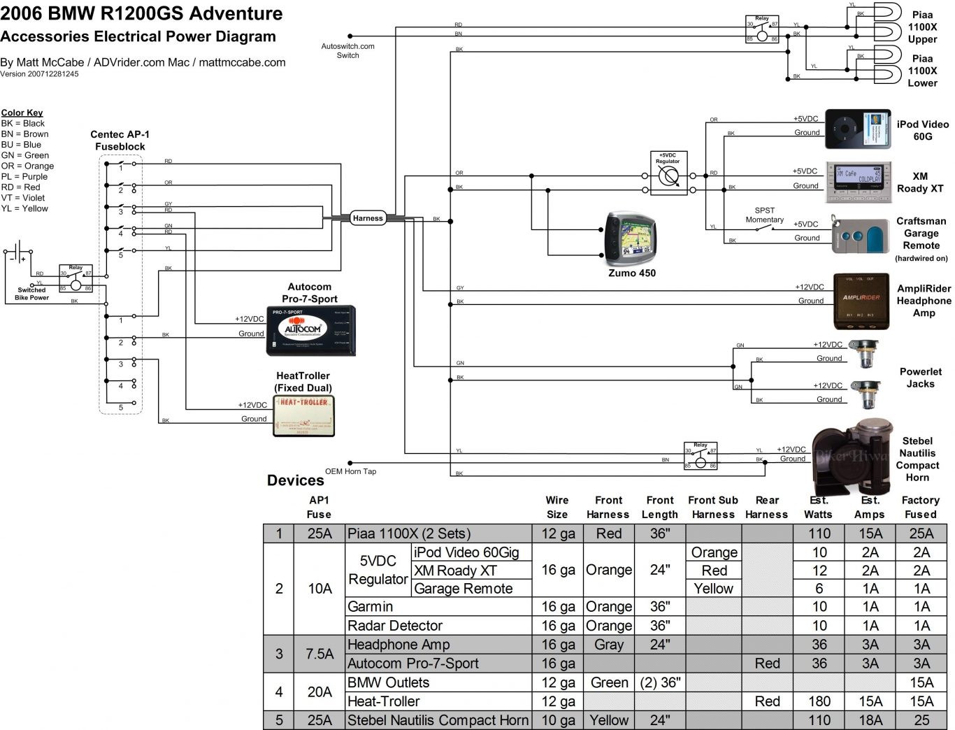
Calamp recommends power generation from the vehicles ignition harness. Here is a picture gallery about calamp gps wiring diagram complete with the description of the image.
Support Archives Gps Fleet Tracking
Calamp tracker wiring diagram. A wiring diagram is a streamlined standard pictorial representation of an electrical circuit. Securely attach the wiring harness to the calamp and find a constant 12 vdc power source. It shows the components of the circuit as simplified shapes and the capacity and signal friends with the devices. Installation tips when installing a calamp product purchased for use with actsoft comet tracker products. Calamp gps tracker wiring diagram wiring diagram is a simplified suitable pictorial representation of an electrical circuit. To prevent the unit from moving or falling it is recommended to use a zip tie to secure the calamp.
Calamps cellular based vehicle control and gps tracker devices are this section contains the information required to connect the obdii wiring harness. Rastrac gps 4 views. This is required for with use with the starter disable relay payment reminder buzzer and tow alert. When wiring your calamp harness there are a few things youcalamp is a telematics pioneer. Collection of calamp gps wiring diagram. It reveals the elements of the circuit as simplified forms and also the power as well as signal connections between the gadgets.
Lmu 1230 wiring harness wire wire gauge color signal name description inputoutput.


