Capacitor units should be capable of continuous operation up to 110 of rated terminal rms 5 voltage and a crest peak voltage not exceeding 2 x 2 of rated rms voltage including harmonics but excluding transientsthe capacitor should also be able to carry 135 of nominal current. 82 external wiring check before the application of the supply voltage all the external cables have to be connected to the io terminals of the eck cabinet.

Lv Capacitor Bank Specs January 2011 Capacitor Electric
Capacitor bank wiring diagram pdf. A number of banks are constructed as a single star double star delta or h bridge configuration. Safety before installation and operation of the apc automatic capacitor bank read this instruction manual carefully. Keep it at the disposal of the people in charge of the installation operation and maintenance. Is a powerful and compact automatic bank. Provide a high level of reliability and security. 4 abb capacitor banks series 100 300 500 700 300r and 500r low voltage capacitor banks the abb capacitor bank.
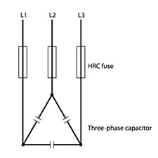
To form high power banks there are three possible wiring or connection modes for combinations of unit capacitors ie. Complete wiring diagrams showing connections of component devices and equipment. Is very easy to install and to operate. Capacitor bank wiring diagram three phase switched and fixed 24 144 kv 16 00 05 00 sheet 1 of 1 distribution construction standards eng. The different possible hv. The capacitor bank is a critical component of apfc panel.
Abb capacitor banks series 100 300 500 700 300r and 500r. Capacitor within a bank may be internally fused externally fused or unfused. Capacitor bank switching. The kpc capacitor bank is wired in parallel with the load. Conventional switching contactor. Only use 75c copper conductors unless the wire connector is marked for alcu then the use of aluminum wire is permitted.
When wiring the unit. In standard 40c ambient or less. Automatic capacitor bank with the guarantee of optimum operation. Contactors are electrically controlled switches for handling higher currents. Voltages of 12 kv. Refer to nec wiring practices for appropriate wire sizes for your application.
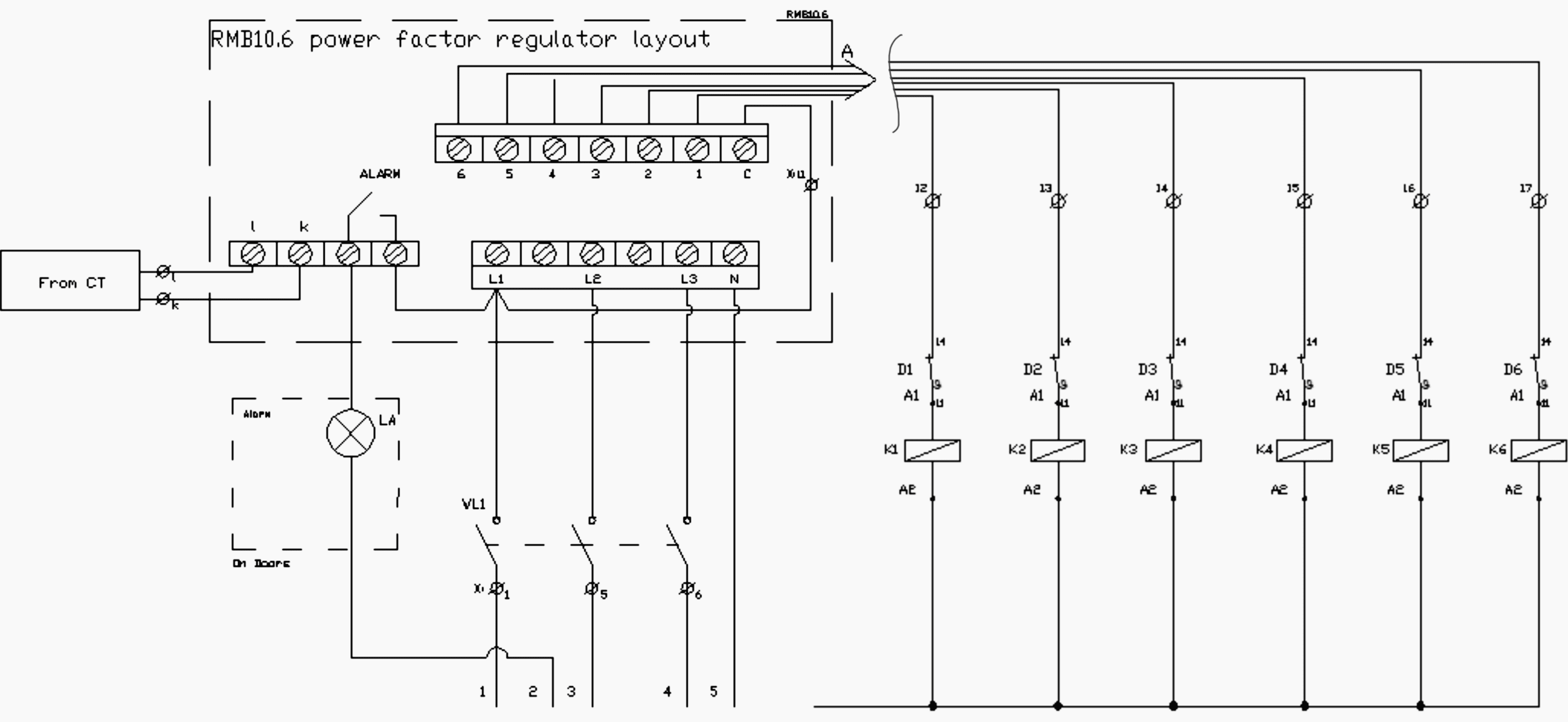
061516 phase wire primary fuse switch lightning arrester capacitor rack bond neutral oil or vacuum switch omit for fixed secondary run. Capacitor bank wiring modes the all film hv. Capacitor bank shall continue to operate upon isolation and loss of a single stage to match reactive power requirements of system as closely as possible. The figure 2 shows a diagram including external wiring and. Capacitors units should not give less than 100 and more than 115 of rated reactive power at rated. Each capacitor can be individually fused with an appropriately sized current limit fuse.
Capacitor generally comes in the form of a single phase unit sometimes three phase but for max. The external wiring of a static capacitor bank is similar to a conventional capacitor bank using switchgears.
