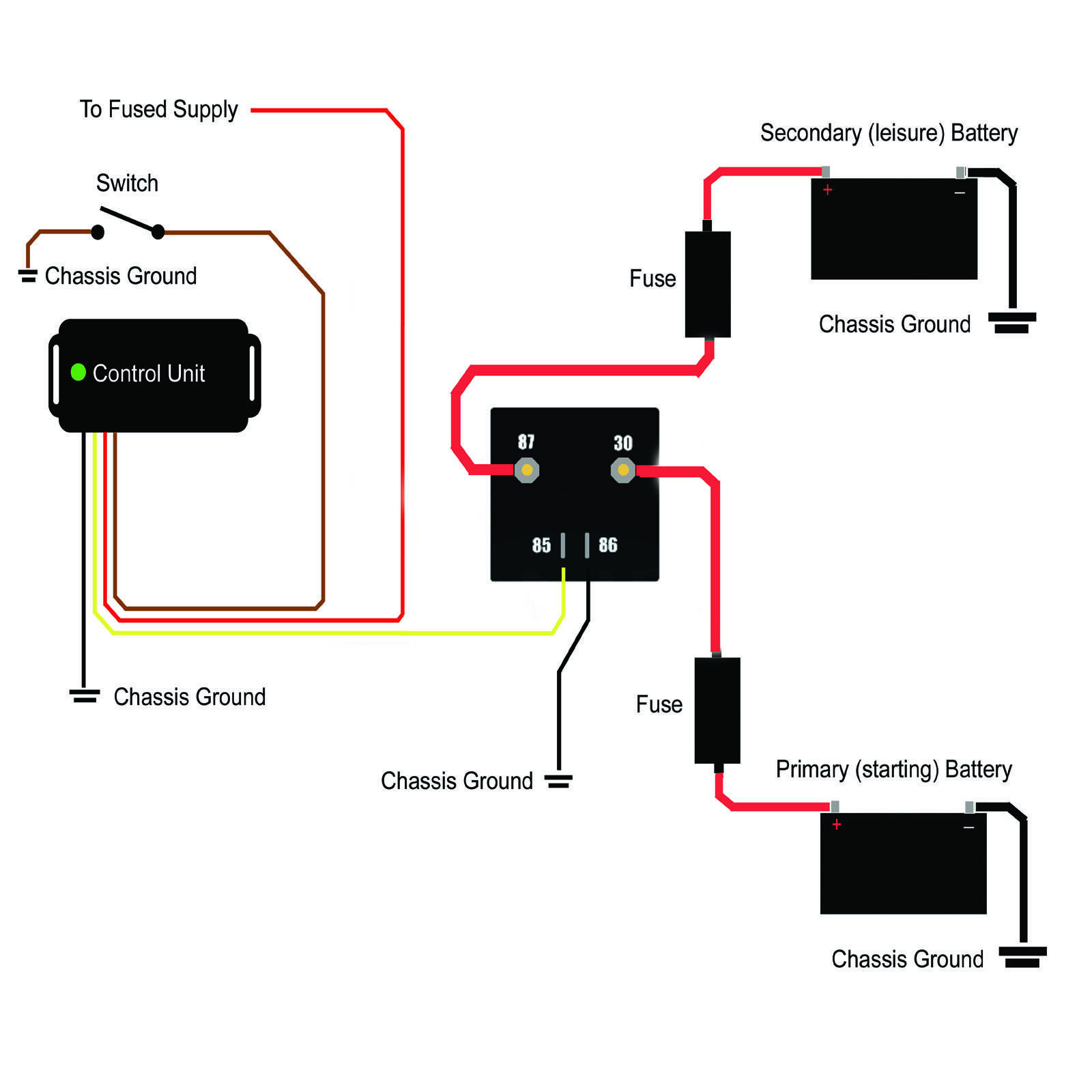
3 mounting and wiring 31 exposition of the ex pc system pc100 figure 1. Test car and service battery b1 and b2 condition test drinking water tank level waste water tank alarm electronic battery separator control 3 way fridge protection fuses control car battery recharging save service battery function.

Cbe Dimmer Switch Wiring Diagram
Cbe pc100 wiring diagram. Extreme caution is advised when handling this device. The led display panel allows power management from one central panel. It provides control of the following functions. For over 40 years the core business of cbe has been 12 and 230 volt electrical systems for recreational vehicles. Car battery test services battery control lights control water pump control external light batteries parallel relay. The cbe pc100 kit is a microprocessor controlled system featuring an led display.
High electrical discharge is possible and can be fatal warning. Pc100 system data transfer with analogous kvm 32 mounting choose a solid place for mounting. Electronics for caravanning and boating. You dont have to wire them all in but for 71 it is nice to know they are easy to add later if you you want to. I istruzioni duso f instructions demploi gb instructions manual d gebrauchsanweisungen pc 100 pc 200 ds 300 3 24 10 17 00016204 070207. System pc100 microprocessor controlled digital system with led control panel having the following functions.
The cbe pc100 controls the water pump isolation lights main power water level display for both waste and fresh water voltage of habitation area battery starter battery status and charging etc.
