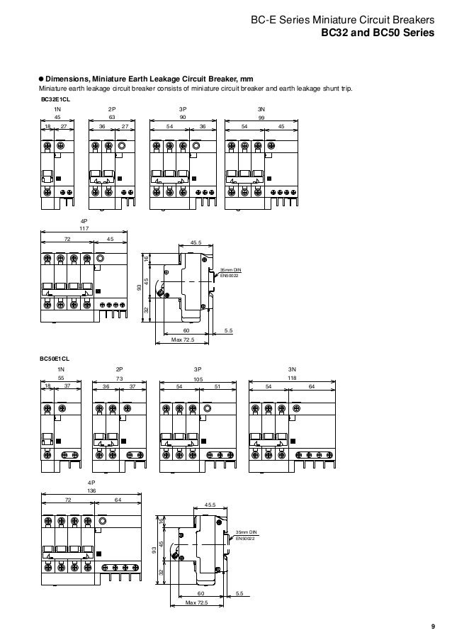
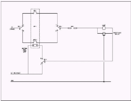
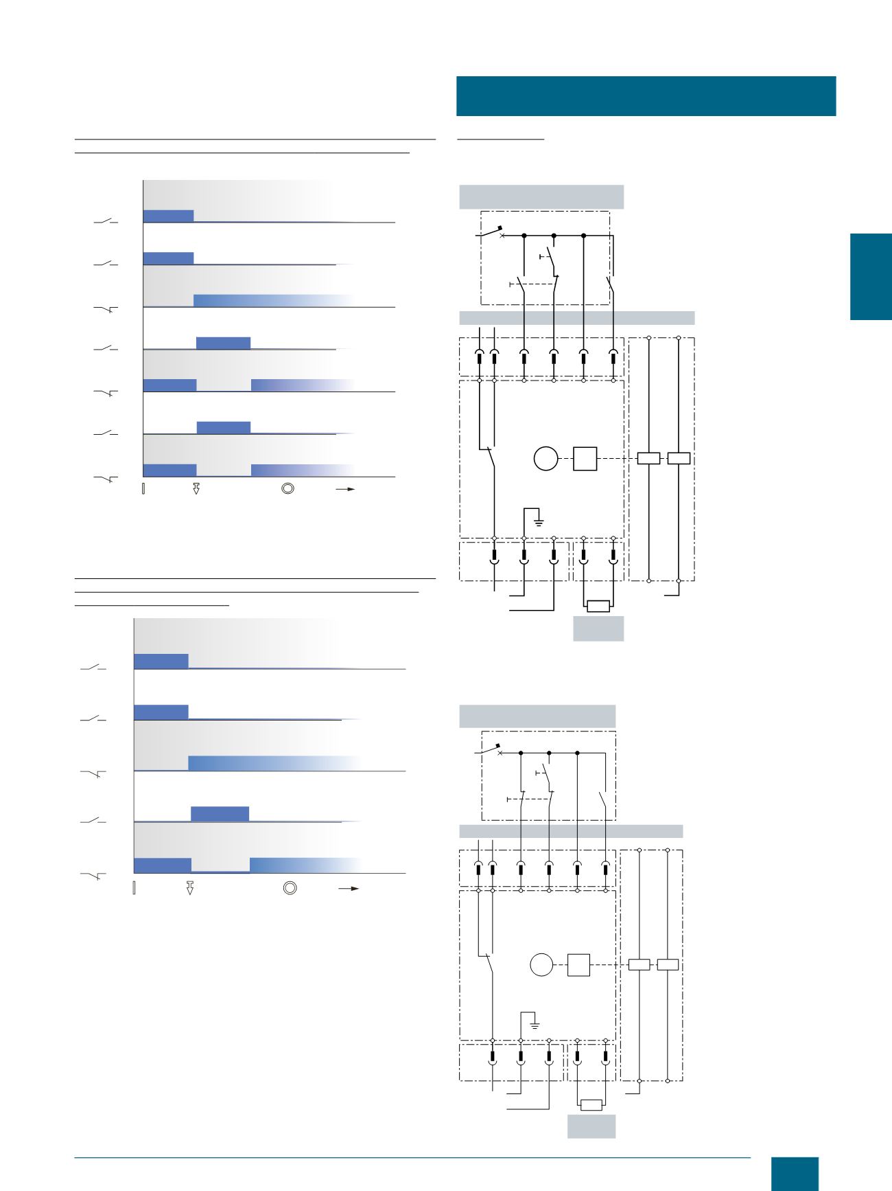
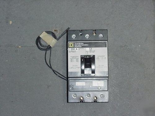
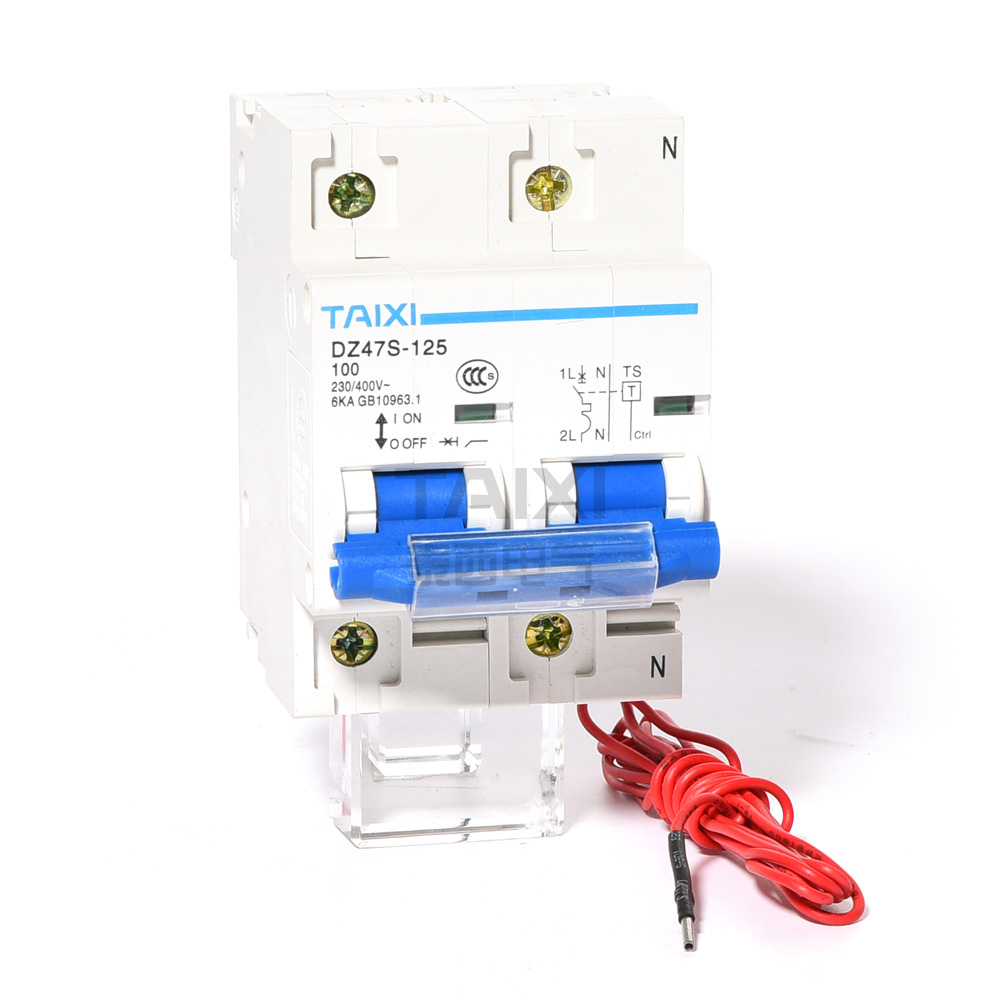
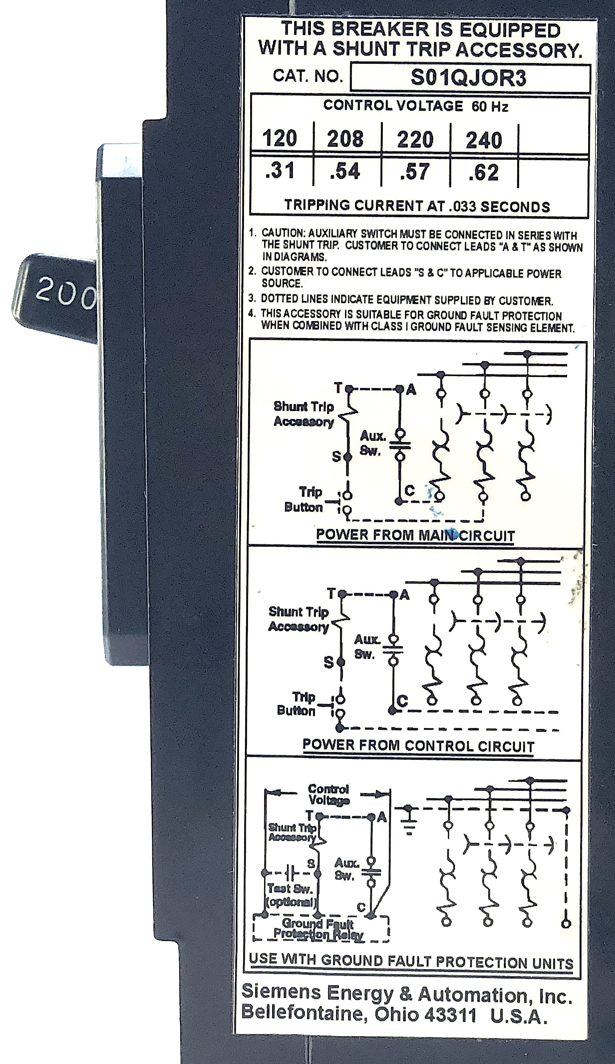
What is the purpose of a shunt trip circuit breaker the main purpose of a shunt trip breaker is that we can easily switch off main circuit breaker form our nearest place in short time and can safe us from electrical accidents. Shunt trip breaker wiring diagram explanation readingrat for throughout square d shunt trip circuit breaker wiring diagram image size 438 x 297 px and to view image details please click the image.

New Wiring Diagram Gfci Breaker Diagram Diagramsample
Circuit breaker shunt trip wiring diagram. Contactor wiring diagram for 3 phase motor. And line wire is controlled with kill switch. The neutral wire is connected to the shunt coil. September 11 2019 by larry a. It reveals the components of the circuit as simplified forms and the power and also signal links in between the tools. In the above mccb shunt trip breaker wiring diagram.
It shows the parts of the circuit as simplified forms and also the power and also signal connections between the tools. It shows the elements of the circuit as simplified shapes as well as the power as well as signal connections in between the gadgets. A shunt trip breaker is a type of circuit breaker that in addition to and other fire suppression systems that can potentially short circuit electrical. The kill switch normally open contacts are used. Also the symbol diagram is shown. The incoming 3 phase 4 wire system supply shown.
So neutral is required also. A wiring diagram is a simplified standard photographic depiction of an electric circuit. Collection of square d shunt trip breaker wiring diagram. Square d shunt trip breaker wiring diagram. But the coil of shunt is 220 vac. Siemens shunt trip breaker wiring diagram shunt trip circuit breaker wiring diagram saleexpert me in square best ideas d and.
A wiring diagram is a simplified traditional photographic depiction of an electric circuit. Here is complete explanation of shunt trip circuit breaker wiring diagram which help you understanding completely. Control voltage frequency operational voltage range 70 110 inrushcontinuous power consumption va opening time ms 24 dc 17 26 4002 25 48 dc 34 53 5003 25 60 dc 42 66 5004 25. Instructions for undervoltage release shunt trip and overcurrent trip switch instructional leaflet il0131087en effective january 2019 table 1. The shunt breaker is 3 pole. Assortment of ge shunt trip breaker wiring diagram.
Collection of shunt trip wiring diagram square d. Here is a picture gallery about square d shunt trip circuit breaker wiring diagram complete with the description of the image please find the image you need. A wiring diagram is a streamlined standard photographic representation of an electrical circuit. Which is used for 3 phase system. I am wiring an ansul fire suppression system and need to know how to tie the micro switches to the shunt trip breakers.
