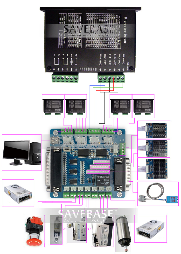
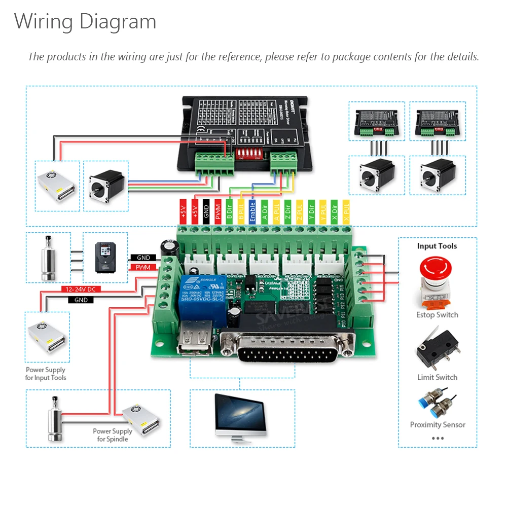
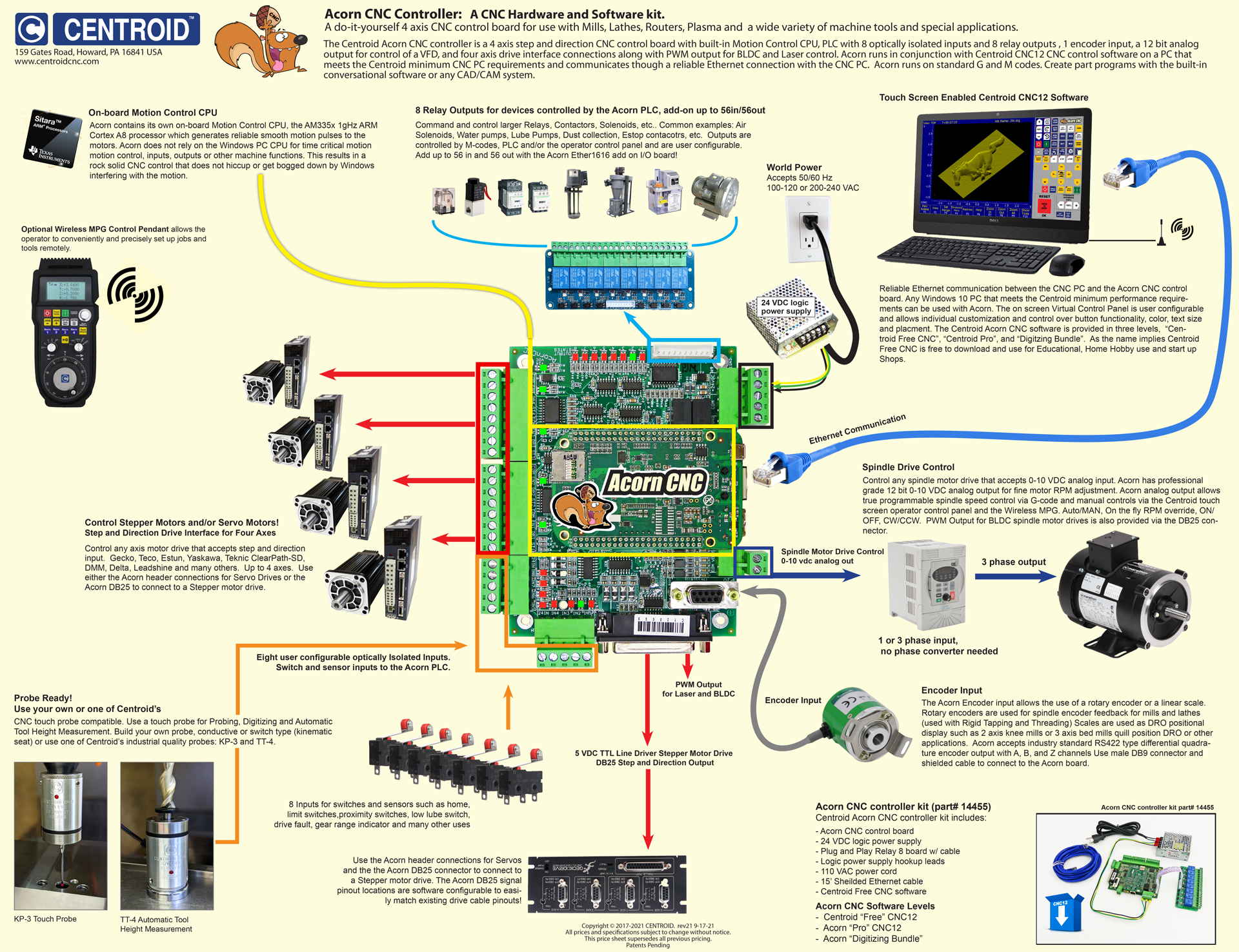
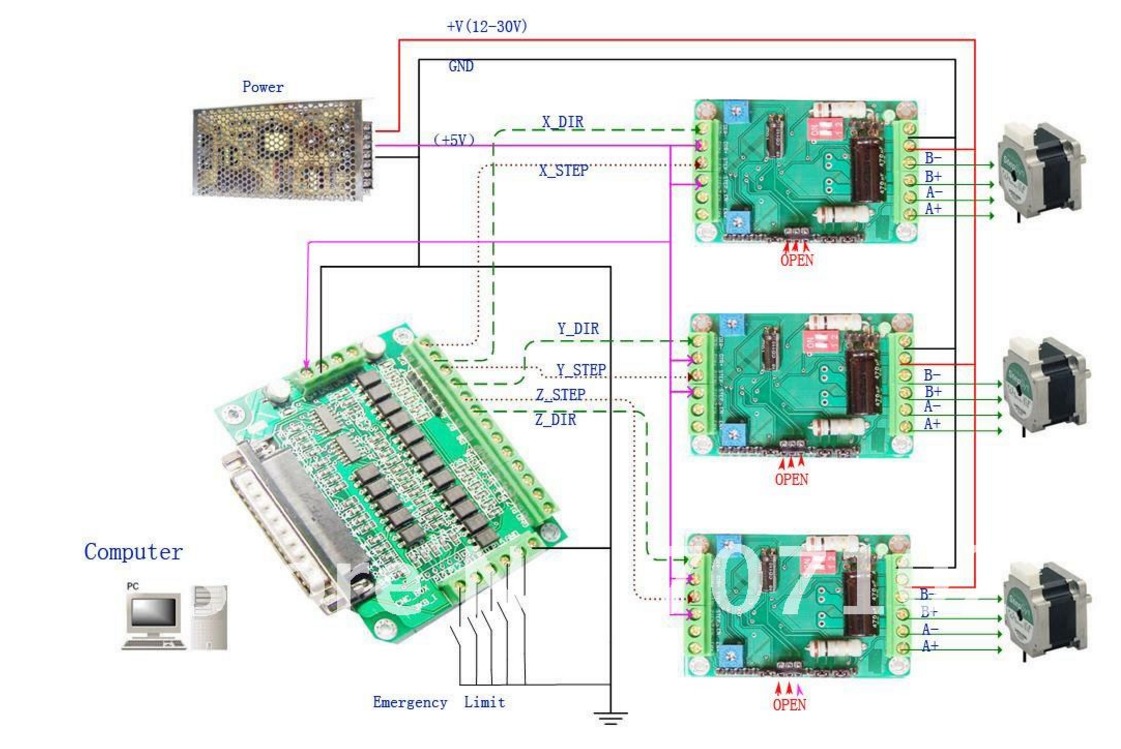
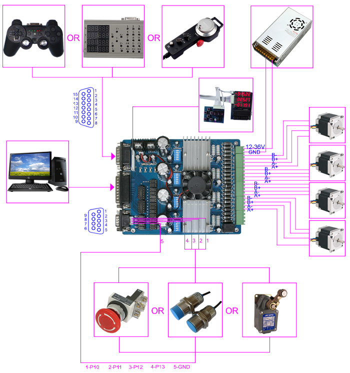
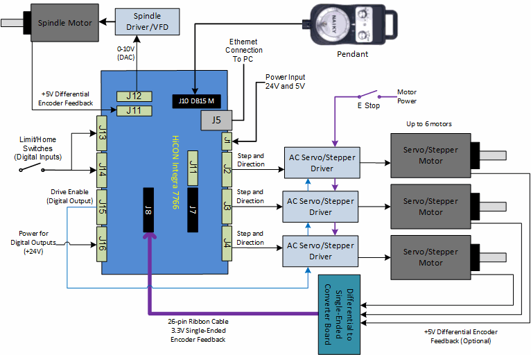
Pin definitions of 5x breakout board. Trying to get into electronics openbuilds pertaining to cnc breakout board wiring diagram image size 750 x 663 px and to view image details please click the image.
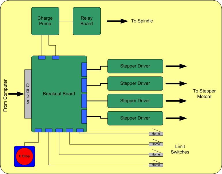
Secrets Of Cnc Control Board Electronics Ebldc Com
Cnc breakout board wiring diagram. Theyre simple and relatively inexpensive. Operation of your cnc or automated machinery. Cnc breakout board wiring diagram awesome allowed in order to my own weblog with this period im going to teach you in relation to cnc breakout board wiring diagramand after this this is the initial impression. Here is a picture gallery about cnc breakout board wiring diagram complete with the description of the image please find the image you need. X axis wiring diagram yel blk wht brn red blu org grn a a b b vcc gnd p1 p3 p2 vcc gnd vcc gnd vcc gnd v c c g n d psu 5v regulated 500ma. The wiring of the parallel breakout board from the output terminals to the driver digital pulse step pulse and direction lines are explained.
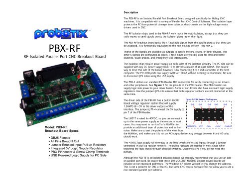
Wiring instruction this diagram can be used as a reference throughout this tutorial. Wiring diagram for power supplies v posv c v com gnd l n l n l n switch mode psus 48 volt with our low inductance nema 23 stepper motors page 3. Zen toolworks cnc machine kits documents repository user manual instruction current settings. Parallel cnc breakout boards connect to your pcs parallel port and convert those signals to screw terminals which you may then use in point to point wiring to connect up the rest of your system. The new parallel breakout board appears a bit different but the process of wiring and testing is the same. Go to the new parallel breakout board to get more information and the wiring diagram.
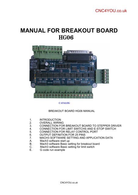
Parallel cnc breakout boards. These are the most commonly used type of breakout board.

