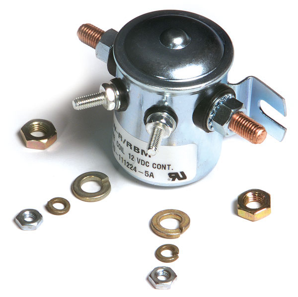
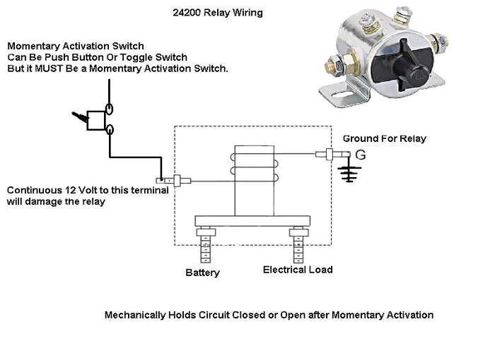
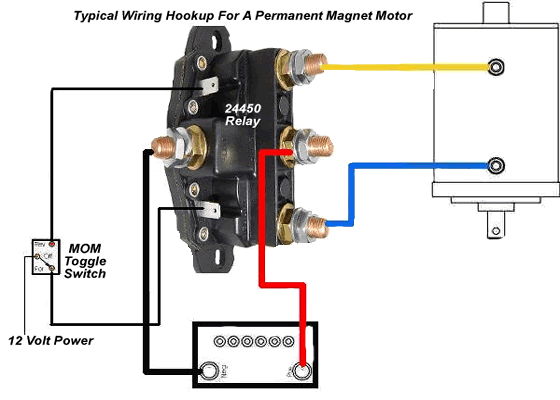
In an engine starting system the ignition switch in the start position may have a rating of 5 amps whilst the starter motor may have a cranking requirement of 200 to 350 amps. The following diagram depicts a solenoid.
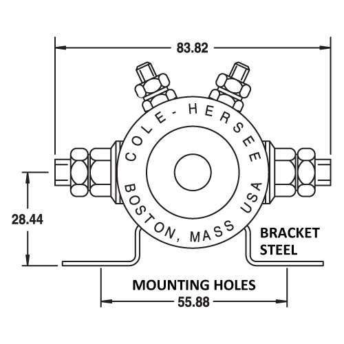
Continuous Duty Solenoid Spst 12v 85a Cole Hersee Australia
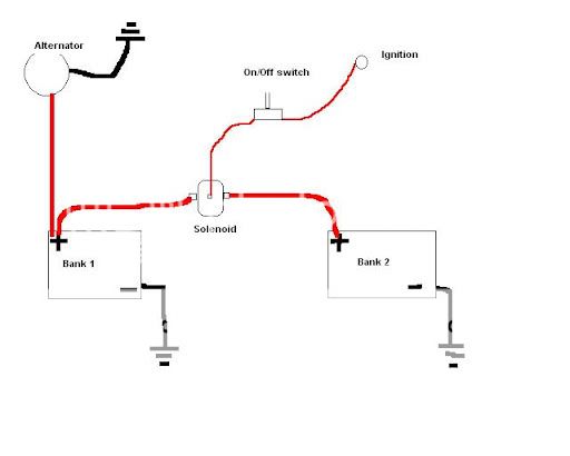
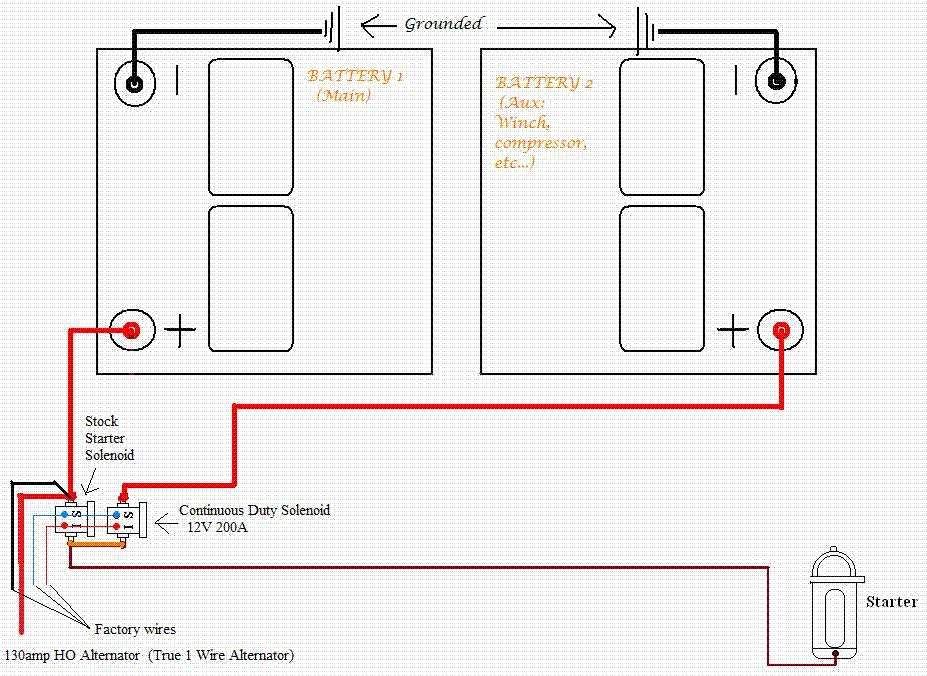
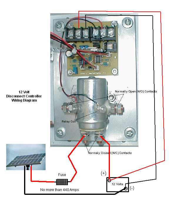
Continuous duty solenoid wiring diagram. How to wire a continous duty solenoid. The voltage is the sum of electrical power produced by the battery. I use 4 gauge ofc cable and 2 150 amp anl fuses. It reveals the elements of the circuit as streamlined shapes and the power and signal links between the gadgets. A wiring diagram is a streamlined conventional pictorial representation of an electrical circuit. D3 solenoid relays d relays solenoids solenoid relays can generally remotely switch a heavier current than is used in regular relays or microrelays.
If you are living in a car van or rv you will need some electrical power. A solenoid is an electromagnetic relay used in a direct current wiring system between a low current capacity switch and a high current load requirement. If i remember correctly one of the small posts on the continous duty solinoids has to be grounded for the coil to engage the contacts i may be wrong so just hook as the picture says and if it doesnt work take a ground to the other small postthese solinoids are different then a starter solinoid in. Continuous duty solenoid wiring diagram inspirational delightful in order to my personal weblog with this time period im going to explain to you with regards to continuous duty solenoid wiring diagramnow this is the primary image. Once energised by the ignition switch the solenoid coil moves the. Continuous duty solenoid relay wiring diagram.
In a real solenoid the spring is often in a different position as this one would get in the way of sealing the pilot hole. You are able to easily step up the voltage to the necessary level utilizing an inexpensive buck boost transformer and steer clear of such issues. By using a solenoid the amount of heavy wiring needed to power the load is reduced since the control circuit mounted on the panel typically utilizes a smaller wire gauge. The plunger is a temporary magnet or soft magnet. It is held away from the core by the action of the spring. Collection of 4 pole starter solenoid wiring diagram.
In this video i install a continuous duty solenoid. Each circuit displays a distinctive voltage condition. In this video we show you how to install a continuous duty solenoid so you can ch.
