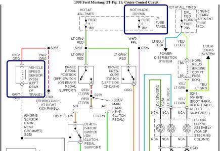
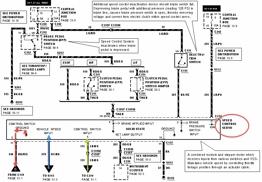
Check the fuses for the brake lights and the cruise control. I have a stripped down dash look that has the required wiring for the brake pressure switch cruise module and all the wiring inside the car.
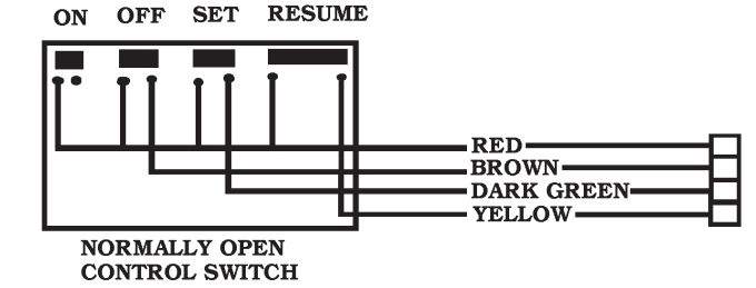
Wiring Switch For Cruise Control
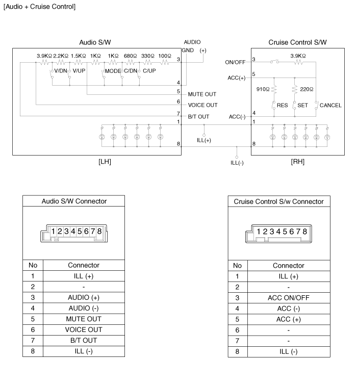
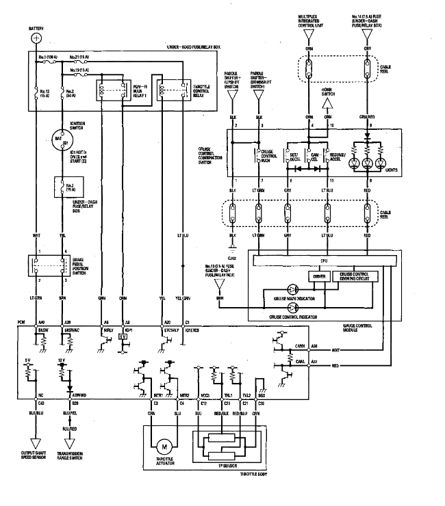
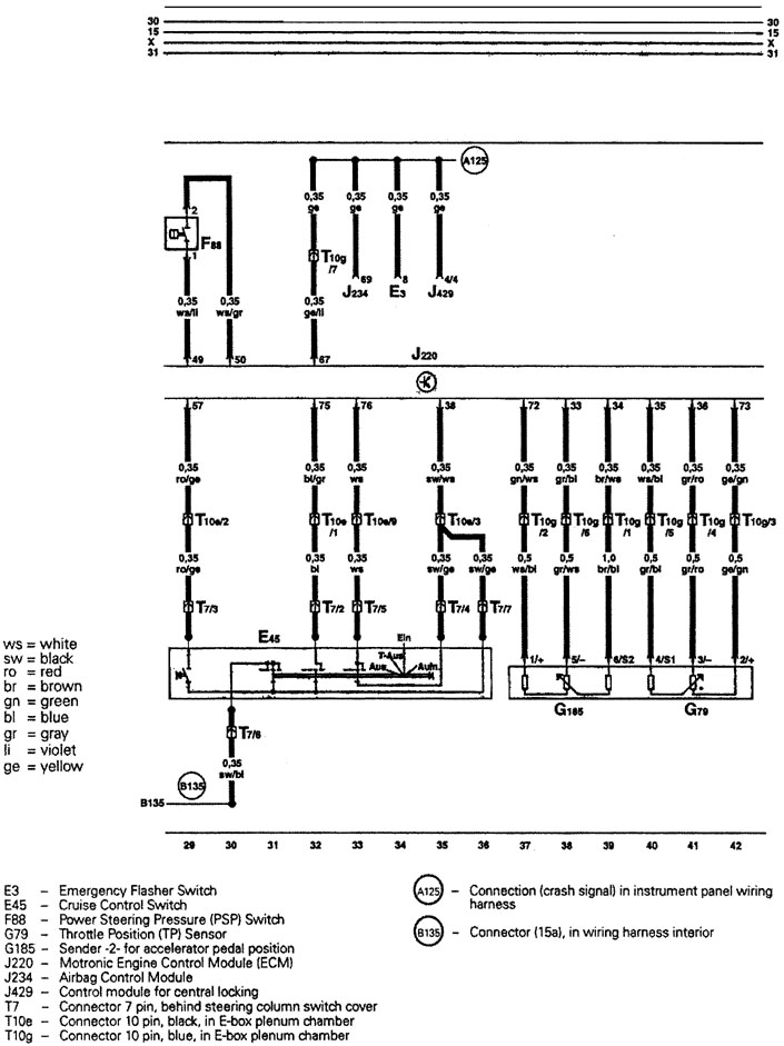
Cruise control wiring diagram. In which the control switch was packaged. Ignition switch harness. Switched 12v pink. Anyone got a decent wiring diagram or even some instructions from a cruise control kitfactory manual for cruise control on an ef. More slack will cause the cruise control to surge or lose speed once set. The wiring diagrams use an alpha numerical grid and an address for each wire entering the harness to show where it comes out.
Hot side of brake. Cold side of brake. If the engine rpms reach a certain rate usually at or above 4000 the cruise control will disengage preventing any possible harm to the engine. Near cruise control module. If any of the 10 switches need to be. Changed after installation of the cruise.
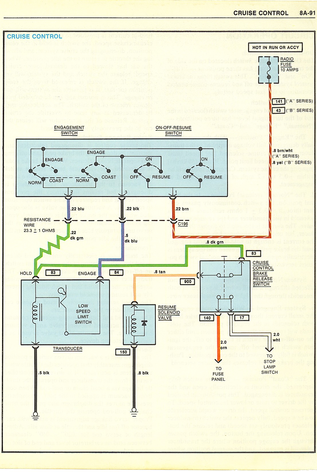
If the brake lights dont work or the fuse for them or the cruise control module is burnt or damaged the system will not work. Learn about the respective current paths circuits data line networks and more. My cars a gli and lacks abs and hence has no wiring for cruise. Ignition switch harness or use hot side of brake. Figure 1 explains the wire coding. 1990 93 chevrolet s 10 pickup cruise control wiring information.
How it works road test and preliminary checks parts testing wire diagrams ford cruise control wiring diagrams. On some vehicles with a manual transmission this is the only wire the cruise control needs to monitor for it to work. With the cruise control switch number 7 will have. Circuit or closed circuit look at label of box. If unsure whether control switch is open. Constant 12v red.
All settings are based on 18 inch slack in cruise control cable. Use the diagram on the underside of the fuse panel lid to locate both of these fuses. Control control switch and the vehicle. If the other end of the wire is on a different page the page number and address will be shown at the bottom right hand corner of the schematic. Shown here are some of the circuits that now handle the operation of the cruise control system. Click here to download a pdf version of this relay wiring diagram.
