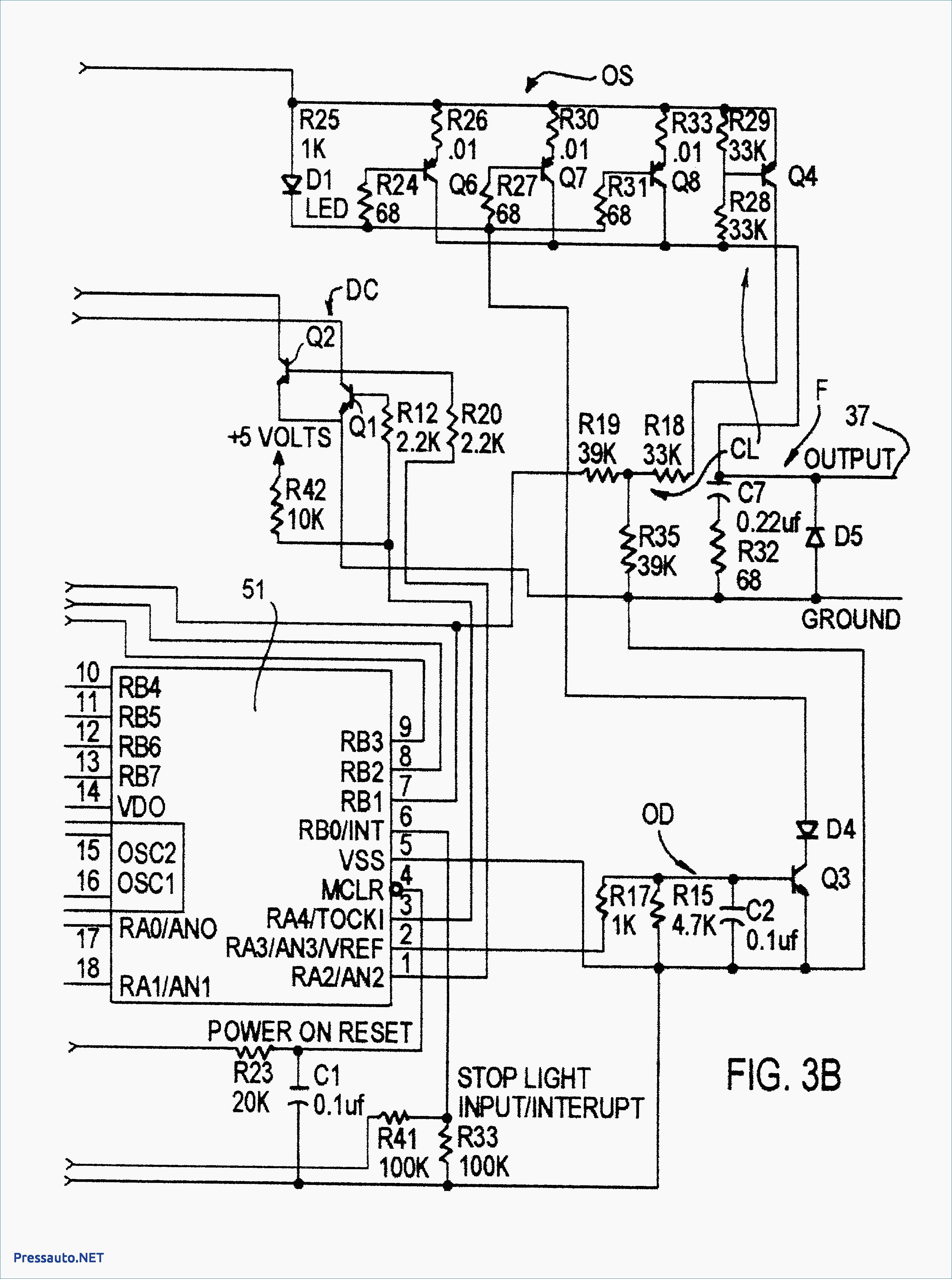
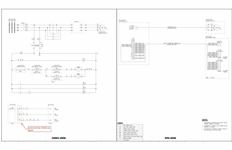
By admin november 30 2017. Wiring diagrams sometimes called main or construc tion diagrams show the actual connection points for the wires to the components and terminals of the controller.
__47718.1575993010.jpg?c=2)
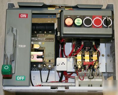
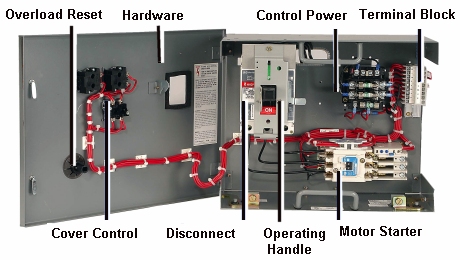
Cutler Hammer F10 Unitrol Size 4 Starter 125a Breaker Type 24 Mcc Bucket 125amp Dw1903 2
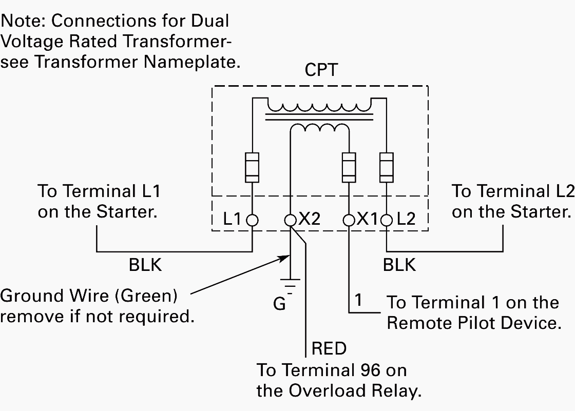
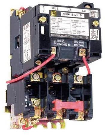
Cutler hammer mcc bucket wiring diagram. Eaton mcc wiring diagrams diagram base website xh 2549 eaton motor starter wiring diagram schematic xh 2549 eaton motor starter wiring diagram schematic reposiciones para ccm. They show the relative location of the components. The usual elements in a wiring diagram are ground power supply cable as well as link outcome devices switches resistors reasoning gate lights etc. Original mcc starter type bucket width inches mm door width inches mm original manufacturer starter type installed in new unit f2100 lever freedom series 13 34 3493 15 58 3970 cutler hammer 1994 to present freedom advantage lever advantage 13 34 3493 15 58 3970 westinghouse until 1994 cutler hammer 1994 to present. Wiring diagrams non reversing starter non reversing starter single phase non combination 260803 d1 figure 1 front view of panel connections for non reversing starter 314 213 reset 97 96 98 95 t1 t2 2t1 4t2 6t3 ol l1 1 l2 3 m a1 a2 1 phase motor t1 t2 1 2 4 ac lines 3 wire control. The leads from the primary of the transformer are connected to l1 and l2 on the starter.
In this way the primary of the transformer is supplied with the same voltage as the powermotor circuit of the starter. Cutler hammer f10 built from 1972 cutler hammer freedom built since 1988 cutler hammer freedom series 2100 built since 1995 a complete plug in unit for adding to an existing mcc includes the plug in unit hinged door isolating divider pan and all necessary installation hardware. Mounting hard ware for old cutler hammer mcc is sold. Cutler hammer mcc bucket wiring diagram. To check out a wiring diagram first you need to recognize what fundamental components are consisted of in a wiring diagram and also which pictorial symbols are made use of to represent them. The common components in a wiring diagram are ground power supply cord and connection outcome gadgets switches resistors reasoning gateway lights etc.
They can be used as a guide when wiring the controller. Figure 1 is a typical wiring diagram for a three phase mag. Figure 4 control power transformer wiring diagram. Eatons mcc aftermarket team not only brings more than 80 years of experience with cutler hammer westinghouse and eaton mccs but also provides replacement solutions for many other brands including allen bradley square d ge itegould and fpe. To check out a wiring diagram first you need to recognize what basic components are included in a wiring diagram as well as which pictorial icons are used to represent them. 8926 1a model a effective 301 freedom 2100 motor control center installation and maintenance manual table of contents part description page 1 general information 2 2 receiving handling storage 4 3 installing control center sections5 4 installing conduit wiring 10 5 incoming line connections 12 6 overcurrent protection.

