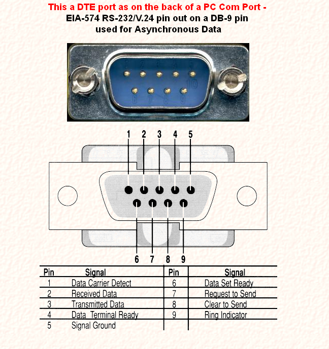
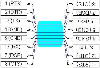
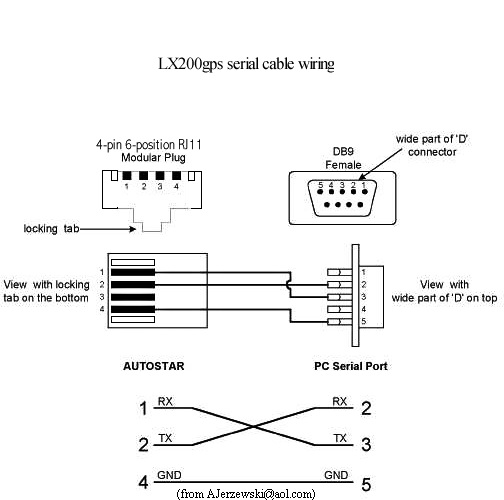
Table 5 2 cable pinouts for rj 45 to db 9 signal console port rj 45 pin db 9 pin signal rts 1 8 7 cts dtr 2 7 4 dsr txd 3 6 3 rxd gnd 4 5 5 gnd gnd 5 4 5 gnd rxd 6 3 2 txd dsr 7 2 6 dtr cts 8 1 8 rts. September 4 2019 by admin.

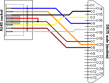
86c241 Rj45 To Db25 Wiring Diagram Wiring Library
Db9 to rj45 wiring diagram. Appendix 5 cable pinouts db9 connector db9 connector table 5 2 lists the cable pinouts for rj 45 to db 9. Cat 5e rj45 wiring diagram. Clip the wire for one of these two strip some of the insulation off and wrap it around the other db9 pin. Because db9 connectors are rarely used on dces there is only a picture of the larger version here. The console port is an rs 232 serial interface that uses an rj 45 connector to connect to a management device such as a pc or a laptop. Ez rj45 wiring diagram.
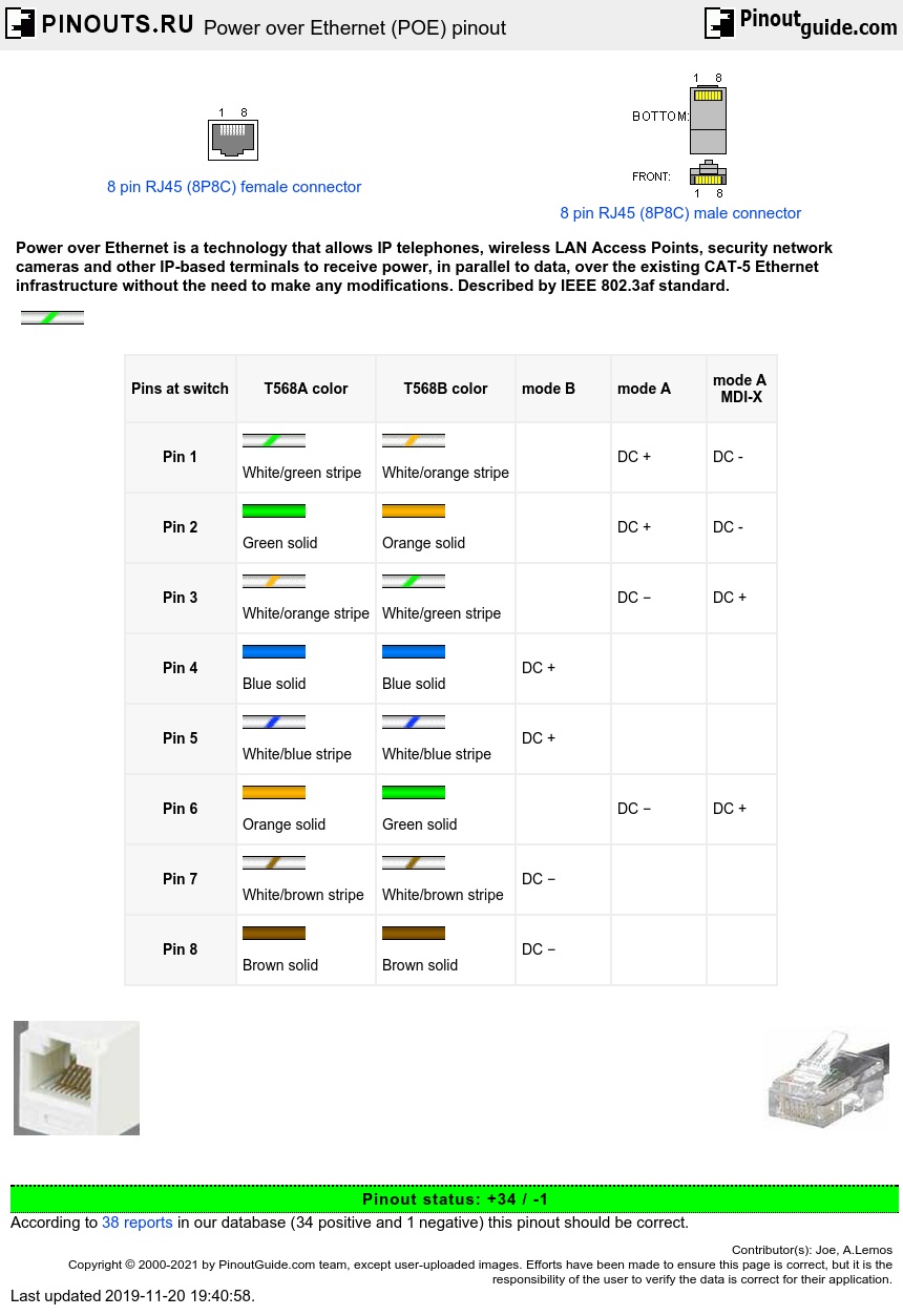
The yost standard defines the wiring scheme for both db9 and db25 connectors. The following diagram shows how each cable by color should be connected. Db9 to rj45 wiring diagram. Pins 1 and 9 are not connected. Cat5 db9 pin green white 8 green 6 orange white 2 blue 5 blue white 5 orange 3 brown white 4 brown 7 the bluewhite and blue must both connect to pin 5 on the db9. The wiring of a yost rs232 to rj45 adapter for a dce is more or less a mirror of the dte adapter wiring.
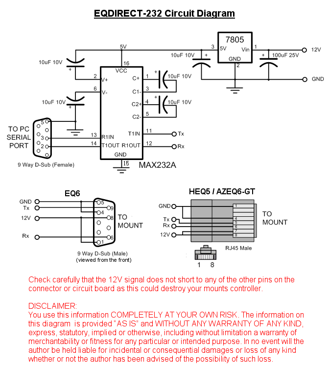
Connecting both rj45 pins 1 and 2 to db9 pin 4 is easy. Db9 female to rj45 wiring diagram. Bt to rj45 wiring diagram. If your laptop or pc does not have a db 9 male connector pin and you want to connect your laptop or pc to the device use a combination of the rj 45 to db 9 female adapter along with a usb to db 9 male adapter. Female usb to rj45 wiring diagram. 21 posts related to db9 female to rj45 wiring diagram.
Dmx rj45 wiring diagram. Connecting both db9 pins 6 and 1 to rj45 pin 3 is also easy. Clip the wire for one of these two strip some of the insulation off and wrap it around the other db9 pin.


