How to wire a 4 pin relay 12 volt dc micro duration. Denso parts are often used in japanese assembled cars including cars manufactured by renowned brands like toyota honda mitsubishi suzuki mazda daihatsu and several others.

Wiring Diagram Car Horn Relay Relay Car Horn Automotive
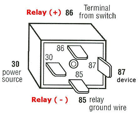
Denso relay wiring diagram. Adding driving lights that come on with the headlight main beam. A few people have asked what gets connected to the different connectors on a relay. Now you can use all the wiring diagrams on. Well since i had an idea but wasnt 100 sure i did some reading and decided to do a quick vid. This simple circuit uses the power feed to the headlight main beam bulb as the trigger to energise a relay. I hope it.
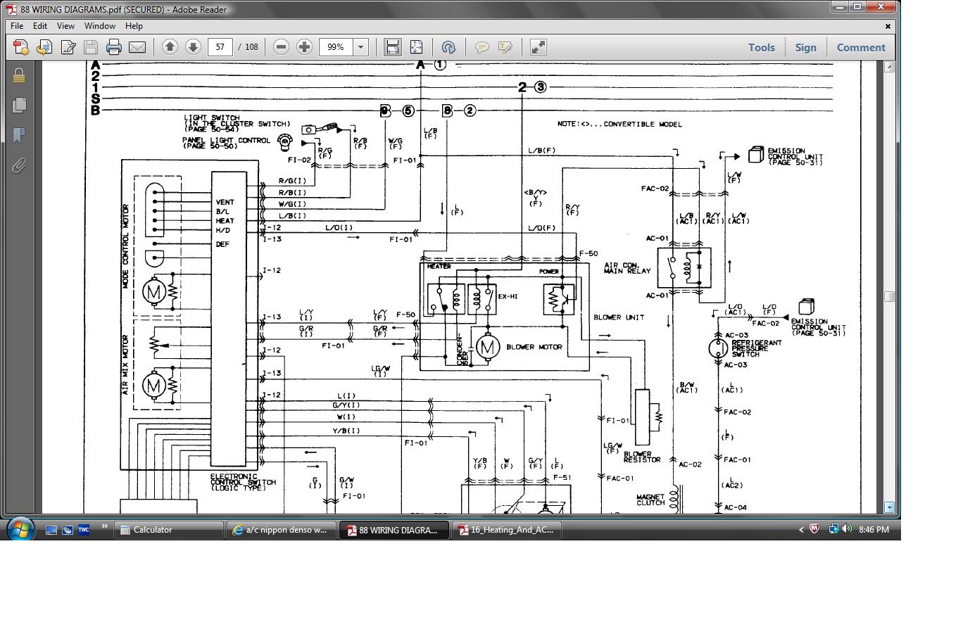
Collection of denso alternator wiring schematic. Example relay wiring schemes. Relays are used to bypass signal wire and directly supply current from battery thus your car wiring remains safe from heating up and burning due to the load of heavy components. A 5 pins type relay. A wiring diagram is a simplified traditional pictorial depiction of an electrical circuit. Wiring diagrams show the wiring for circuits not the parts of the car that the circuits just happen to be fastened to.
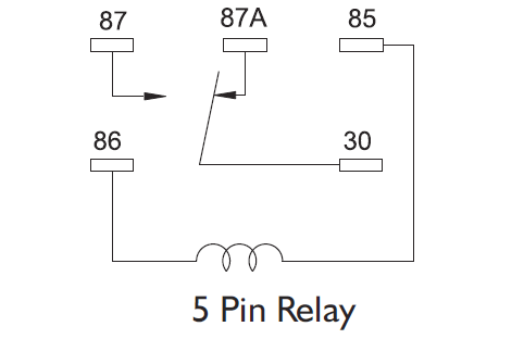
061700 3771 circuit diagram cars trucks question. A fifth normally closed contact pin can be added. Two coil pins two normally open contact pins. How to test a 3 4 or 5 pin relay with or without a diagram duration. There are no wiring diagrams for the steering column. Rocky x tv 20251 views.
It reveals the elements of the circuit as simplified forms and the power and also signal connections in between the tools. The following diagrams show some common relay wiring schemes that use 4 pin iso mini relays. Relays that normally used in electronic circuits are spdt and dpdt types due to their flexibility in controlling circuit switching. The denso relays are just the iso micro version of the standard bosch relay about which there are lots of really good sites. In the next section a demonstration on identifying the pins of a relay from spdt or dpdt type without referring to its datasheet will be illustrated. Relays are the integral component of any.
When using this switch with the universal stainless wiper motor 911 23502 the switch will be wired from the s terminal on the motor to the l terminal on the switch. Universal wiper switch wiring diagram here you are at our site this is images about universal wiper switch wiring diagram posted by benson fannie in universal category on sep 17 2019. Its just a slightly different pin format but all the principles are the same. The high current circuit in this relay feeds.


