A direct online starter consits of two buttons a green button for starting and a red for stopping purpose of the motor. The direct on line motor starter dol consist a mccb or circuit breaker contactor and an overload relay for protection.

Motor Starter Wiring Diagram
Dol starter panel wiring diagram. Wiring of the direct on line dol motor starter 1 three phase supply 230volt coil see wiring diagram. To prevent damage to the windings due to the high starting current flow we employ different types of starters. The simplest form of motor starter for the induction motor is the direct on line starter. These two buttons ie. The wiring diagram for a dol stater is shown below. All connection i shown with complete guide.
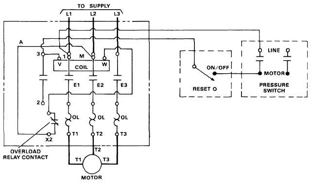
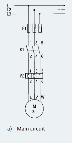
In the above three phase dol starter wiring diagram. The r y and b phase are connected through mccb to the contactors. Akrtechnical dolstartercontrolwiring hi i am abhilash k r welcome to our malayalam youtube channel akrtechnical. Dol starter control power wiring diagram overload indicator wiring in malayalam. A2 14 18. If a starter incorporating a tesys k series contactor lc1k is used then the connections between 9514 and 96a2 are made internally.
Green and red or start and stop buttons control the contacts. In the below dol starter wiring diagram i shown a molded case circuit breaker a magnetic contactor normally open push button normally close push button switch thermal overload relay motor trip indicator and 3 phase motor. The dol starter comprises of an mccb or circuit breaker contactor and an overload relay for protection. The contactor has 3 types of contacts. 13 17 with a flying lead to be connected to overload terminal 95. This is the wiring diagram of a dol starter mccb or circuit breaker.
1 the following links are pre fitted to the starter. All other control and power connections have to be made by the installer. This diagram illustrates possible wiring using a tesys d lc1d contactor and tesys lrd overload lrd and stop control is assumed to be by operation of the stop button on the overload.


