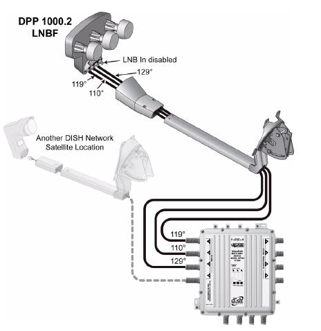
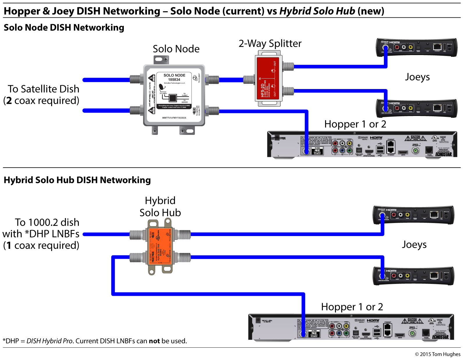
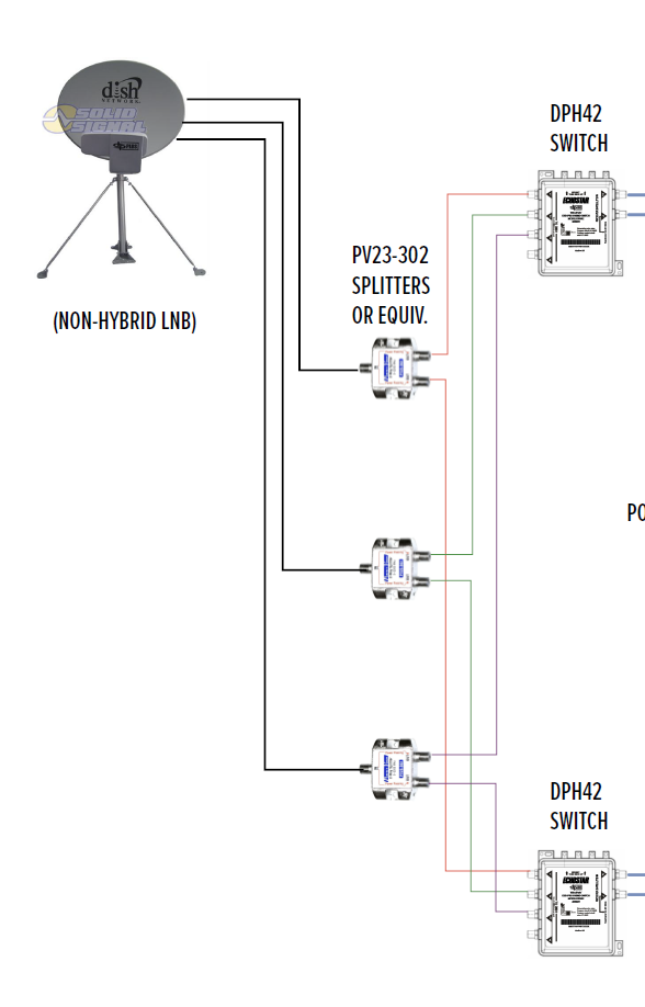
Youll need dpp44 switch diagram is simple check dish web site basically. Replace the dpp44 switch first.

Directv Dish Question Archive Through August 03 2010
Dpp44 switch wiring diagram. 6 introduction the dish pro plus 44 switch dpp44. Do i have to change the satellite settings. How to wire bell tv satellite wiring diagram. Dpp dish pro plus bell tv installs page 5 canadian tv computing and home theatre forums. This circuit is wired the same way as the 3 way lights at this link. When i switch cables at the switch the problem stays with port 1.
Make sure that the mounting location is stable and that you fasten. Refer to the wiring diagrams that begin on wiring diagrams on page 13. I tracked this down to port 1 of the dpp44 switch. Bell expressvu sw44 switch wiring. For 727ºw 77ºw 1187ºw and 121ºw orbits it is recommended that these orbits be connected to the to dish port 4 connection. Order from the lnbfs to the dpp44 switch.
3 way switched outlet wiring. The source is at the sw1 where the hot is connected to. It goes to 1 of 50 test everytime. In this diagram two 3 way switches control a wall receptacle outlet that may be used to control a lamp from two entrances to a room. I moved the receiver that was having problems to the other location and it works ok there. Add to cart best offer.
Ken excellent diagrams and thanks for taking the time to find them. My bell satellite does not receive any channels now in phoenix az. Orbits 615ºw 110ºw 119ºw and 129ºw can to connected to any open. 6 introduction the dish pro plus 44 switch dpp44 features dish pro plus refer to the wiring diagrams that begin on wiring diagrams on page satellite. Mount the dish pro plus 44 switch onto the side of a building or on some other sturdy structure. How do you hook up 4 bell satellite receivers using the sw44 switch.
Dish 1000 dp 500 lnbf assembly 1000 bracket dp dualsi ngle dpp44 switch 4 dual w dpp separators or 4 single tuners 14 615º 727º and 77º 3 orbital locations eastern arc assembly. Select that dpp44 and it will show you a wiring diagram for. Now i cannot get the check switch to work correctly on the receiver connected to port 1. Mounting and connecting the switch refer to the wiring diagrams starting on page 17 and complete the instructions below to mount and connect the switch to your system. Three wire cable runs between the switches and the outlet. Ken awesome diagram and info.
If it wont work with 1 wire with the non plus lnb what will i need to hook up the 6 pvrs.


