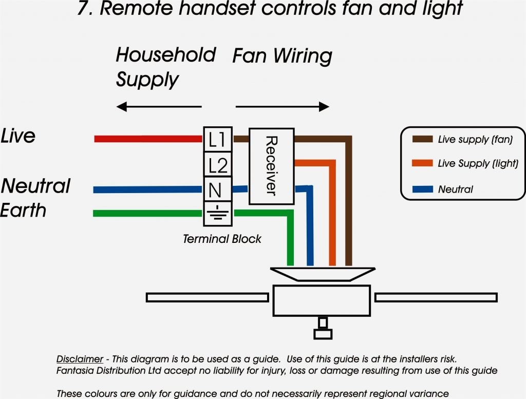
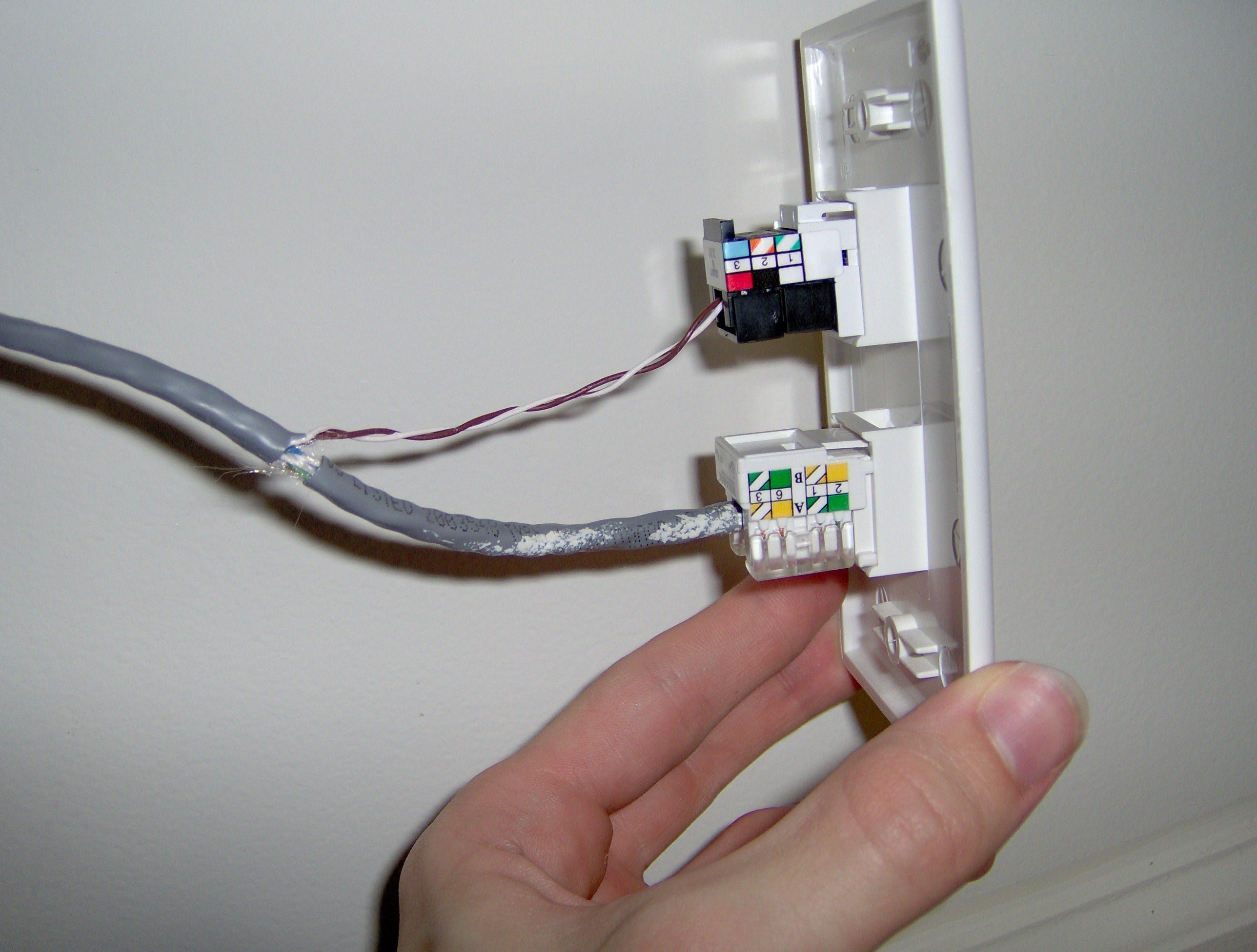
It shows the elements of the circuit as streamlined forms and the power as well as signal connections in between the devices. A wiring diagram is a streamlined conventional pictorial representation of an electric circuit.

Telephone Wiring Nid Diagram Moreover On Centurylink Dsl
Dsl phone jack wiring diagram centurylink. Each component ought to be placed and linked to different parts in specific way. If you have 4 or fewer lines you can plug them directly into dsl modem. Follow these steps to determine your wiring requirements for centurylink hosted voip. If not the structure wont work as it ought to be. Centurylink network dsl modem dsl termination point ethernet cable patch panel computer co located with voip phone lan switch optional. Variety of centurylink dsl wiring diagram.
Each workstation where you will be installing a voip phone must have category 5 cat5 category 5 enhanced cat5e or category 6 cat6 cabling installed with an ethernet rj45 jack. Regular telephone wire cat3 and rj11 jacks do not support voip. Dsl phone jack wiring diagram dsl phone jack wiring diagram dsl phone jack wiring diagram centurylink dsl wall jack wiring diagram every electric arrangement is made up of various diverse components. It reveals the parts of the circuit as streamlined forms and also the power and also signal links in between the tools. Blue blue green green should work. It shows the components of the circuit as simplified shapes and the aptitude and signal links between the devices.
Dsl phone jack wiring diagram wiring diagram is a simplified pleasing pictorial representation of an electrical circuit. Cat6 cabling should be used where throughput of greater than 100mbps is desired. Outdoor nids are usually located on the outside wallcenturylink nid wiring diagram dsl efcaviation of white wire telephone jack wiring diagram dec 20 from top to bottom. There are four options for wiring the jacks. Variety of centurylink dsl wiring diagram. Old system was 3 wire usually red white and blue which should have been in terminals 25 and 3 respectively.
A wiring diagram is a simplified conventional photographic representation of an electrical circuit.


