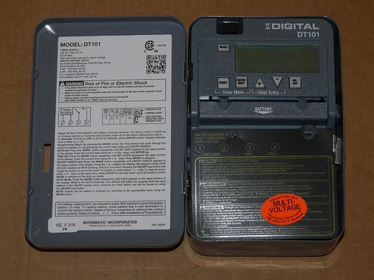
Dt101 shows neutral to terminal 1 line to terminal 2 a load wire connecting terminals 1 and 4. Buy the item featured in this video at 800 337 1720 or visit.

Ew 0581 Wiring Diagram Intermatic T101 Timer Free Diagram
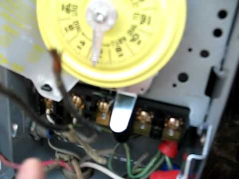
Dt101 timer wiring diagram. Timer controls in wall controls photocontrols sensors weatherproof covers surge protection hvacr pool and spa grässlin timer controls sensors. How to wire and connect a intermatic pool pump timer t101r duration. Mounting bracket for intermatic standardized timer mechanisms 156t1978a extrareplacement trippers 1 on and 1 off 156t1978ad12 12 pack of 156t1978a trippers for t100 t7000 and. T101 had white wire to terminal a black wires to terminal 1 and 2. T100 series 40 amp 24 hour indoor mechanical timer with double pole single throw switching 120 vac gray. 110 125 volts 60 hz.
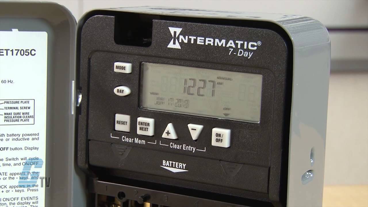
Wire size max 8 awg. 30 amp 7 day spst 1 circuit astronomic time switch. Replacing a t101 timer with a dt101 timer and the wiring is different. The timer uses a gr label to identify its green colored ground screw. Depending on how the timer is switched internally if you look at the wiring diagram the jumper wire between terminals 2 and 3 are carrying the 120v to terminal 3 regardless if the timer is on or off. Wiring diagram pressure plate terminal screw make sure wire insulation clears pressure plate minimum copper wire size awg max.
Intermatic prints the labels above each terminal. Step 5 identify each wire terminal using the numbered labels 1 through 4 for line and load terminal identification. Intermatics et1100 series time switch timing relay presented by katie rydzewski for galco tv. Dt series 1 circuit 20 amp 24 hour indoor surface mount timer with battery backup gray. Each wire set contains two insulated and one bare wire. T101 had white wire to terminal a black wires to terminal 1 and 2.
30 amp 7 day 2xspst 2 circuit astronomic time switch. 14 12 10 8 15 20 30 40 60 60 60 75 12 1 2 2 2 12 3 5 na clock motor. How to wire p1353me intermatic pool timee. Insul ation tempc 75c insulation max. Two wire sets enter the timer. Replacing a t101 timer with a dt101 timer and the wiring is different.
Motor load hp single phase 3 phase 120 v. Dt101 shows neutral to terminal 1 line to terminal 2 a load read more. This may be fine for a 120v circuit however it is not safe to do on a 240v circuit unless the timer does not carry voltage to that 3 terminal when it is on. Knockout dimensions bottom 2 combination 12 34 knockout dimensions backside 1 combination 12 34.
Gallery of Dt101 Timer Wiring Diagram