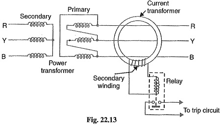
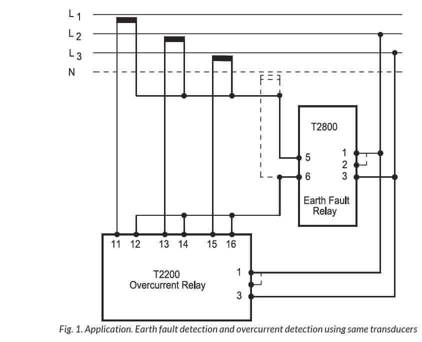
2 no oc relay 1 no ef relay for over current and earth fault protection. The output of these transformers is given to the relays.
6c7cf8c Buchholz Relay Transformer Wiring Diagram Control
Earth fault relay wiring diagram. Earth leakage relay elr requirement according to iec 60947 2 annex m. The earth fault relay operates only for the internal fault of the protective zone. This is an economical version of 3 ol and 1 el type of protection as one overcurrent relay is saved. Direct ground current sensing 3 wire or 4 wire system 7 ground fault protection applied to 4 wire 8 double ended secondary substations direct ground current sensing single point grounding 8 modified differential residual sensing method 10 fixed mounted wl circuit breakers 11. The relay is designed for sensing the fault current which is 15 more than that of the rated winding current. Miniature circuit breaker an overview earth leakage circuit breaker wiring earth leakage circuit breaker elcb circuit breaker wiring diagram mcb mccb elcb kt 4083 wiring diagram elcbearth leakage circuit breaker wiring diagram relay fault protection angle white png pngeggearth leakage circuit breaker diagram base site fldiagram santuarioannunziata itold vole operated elcbsworking principle of.
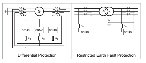
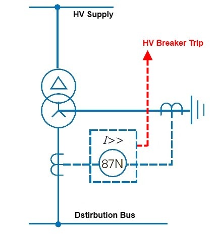
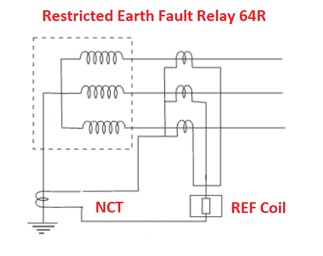
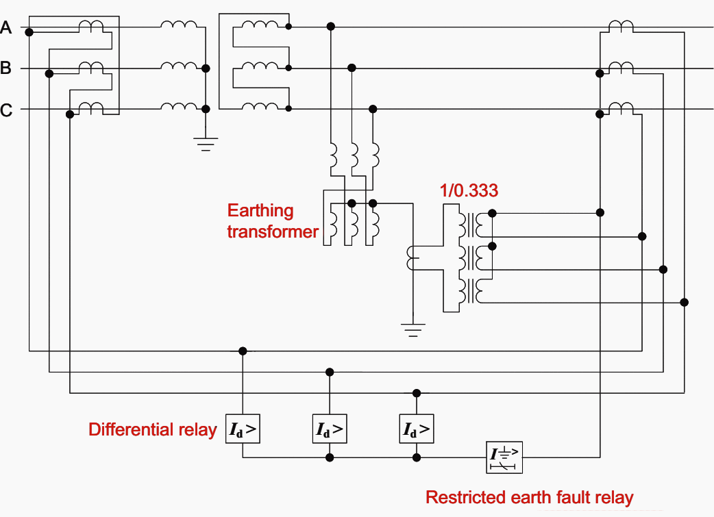
Overcurrent relay instantaneous overcurrent relay earth fault relay etc. Such settings protect a restricted portion of the winding. It reveals the components of the circuit as simplified shapes and also the power and signal connections in between the tools. If the contact is broken with the relay at rest then the relay is referred to as normally open no and if. Hence the name restricted. The earth fault relay must be very sensitive for sensing the fault.
Rgu 2 earth leakage relay. Relay wiring diagram also phase failure circuit breaker distribution board directional earth fault relay operation earth fault indicator circuit. The relay contains preset value if the current or voltage exceeds the preset value then the relay operates the associated circuit breaker then the fault will be cleared. Restricted earth fault relays. For fault involving ground reliance is placed on earth fault relay. With the protection scheme as shown in figure complete protection against phase and ground fault.
A wiring diagram is a simplified traditional pictorial depiction of an electrical circuit. Assortment of 12 volt relay wiring diagram. Their most common application offshore is on transformer windings. Geoff macangus gerrard in offshore electrical engineering manual 2018. Sh 3286 phase failure relay wiring diagram schematic. For restricted earth fault relays both sensitivity and stability tests are necessary as these relay schemes may be subject to through fault currents owing to faults in the electrical system outside their zone of operation.
The iso mini relay we have looked at above has 4 pins or terminals on the body and is referred to as a make break relay because there is one high current circuit and a contact that is either open or closed depending upon whether the relay is at rest or energised.

