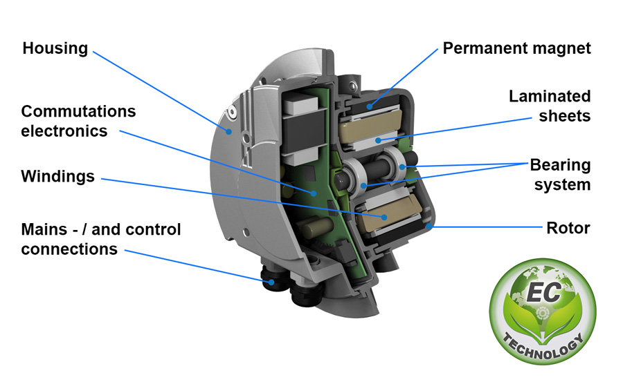
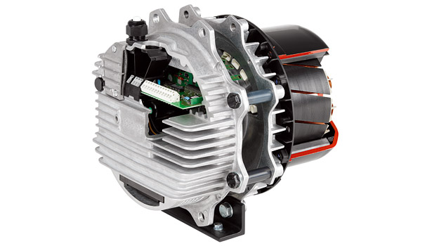
Ac80 ac90 ac100 single phase motors. Ec motors are very high efficiency and maintain a high efficiency level at part speed.

Unique Wiring Diagram Garage Door Motor Diagram
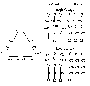
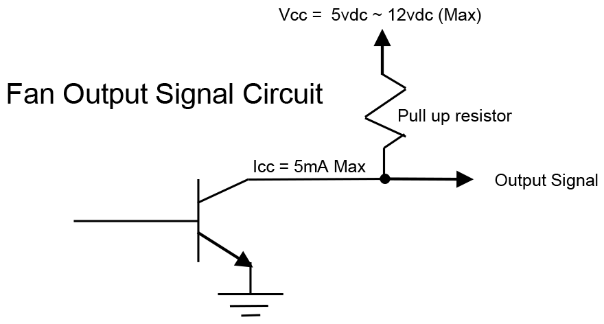
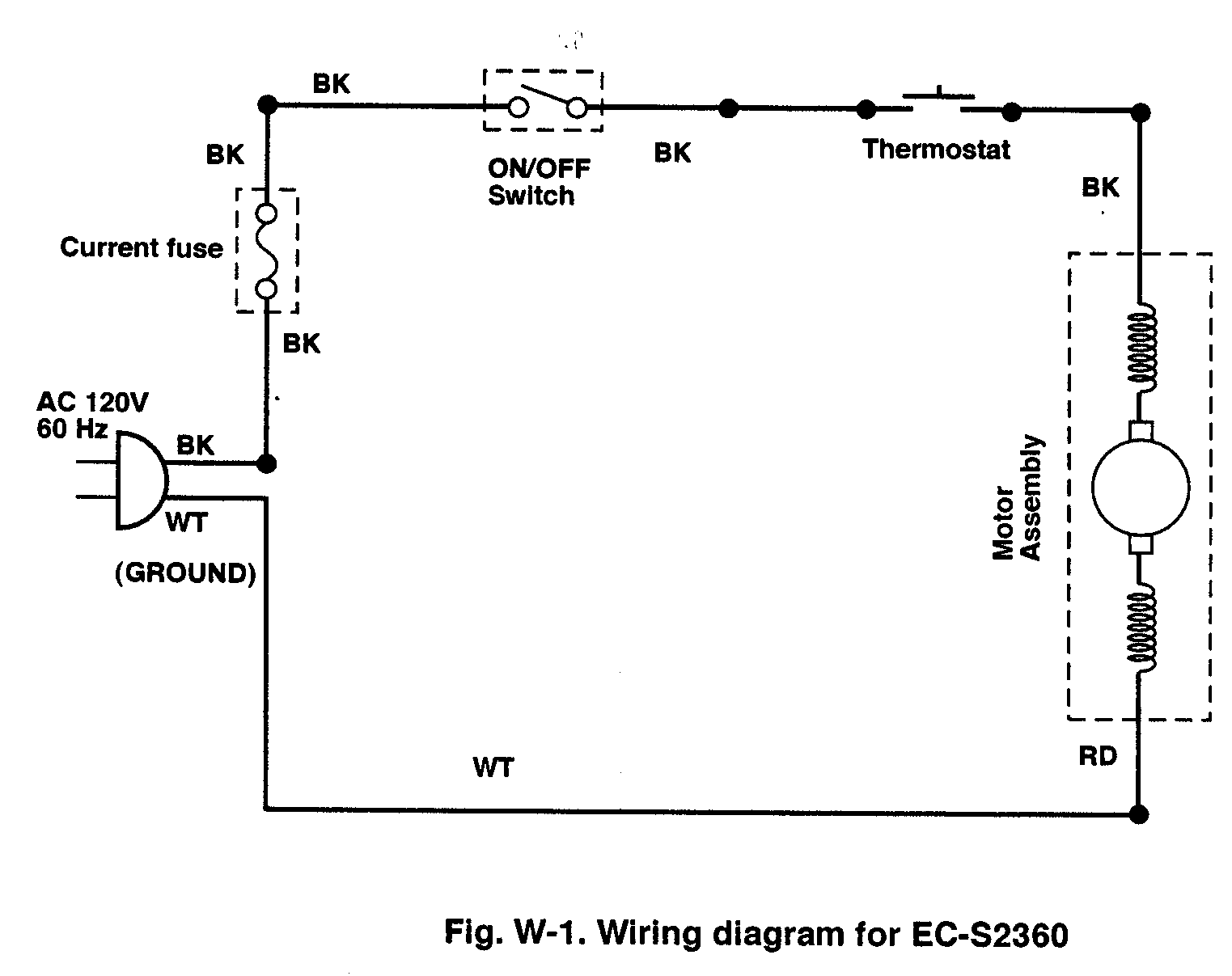
Ec motor wiring diagram. The 3 control wires are not used. 4 ec motor wiring diagrams potentiometer dial only see figure 6 motor features a potentiometer dial located on the side of the motor allowing the user to make necessary speed adjustments with a small flat tip screw driver. It seems like most ec motors offer the ability to control speed either with variable voltage or pwm but looking at a few datasheets i cant see any requirements for the pwm signal other than details about duty cycles. Ecm motor wiring diagram chevrolet s wiring diagram ecm motor wiring diagram wiring diagram contains numerous detailed illustrations that present the connection of various things. This will cover both how to connect. M3g074 motor single phase m3g084 motor single phase m3g112 motor 3 phase for single phase motor apply single phase supply as shown above.
Rm eci cn1003 emc standards interference emission en61000 6 3 interference immunity en61000 6 2 harmonics en61000 2 23 controller wiring diagrams fan wiring diagrams ac fans ac controllers ec fans. Always use wiring diagram supplied on motor nameplate. Ec motor wiring diagram supplement october 2019 type p ec motor part numbers 100175 615267 615269 type r ec motor part number 100200 fan mounted speed control external signal 0 10vdc speed control fan mounted speed control external signal 0 10vdc speed control. This means that in most cases they use from less than one third to one half of the electricity used by the traditional shaded pole induction motors used in the ventilation and refrigeration industries which in turn translates into lower operating costs and short payback periods. Ac80 ac90 ac100 single phase motors. 3ø wiring diagrams 1ø wiring diagrams diagram er9 m 3 1 5 9 3 7 11 low speed high speed u1 v1 w1 w2 u2 v2 tk tk thermal overloads two speed stardelta motor switch m 3 0 10v 20v 415v ac 4 20ma outp uts diagram ic2 m 1 240v ac 0 10v outp ut diagram ic3 m 1 0 10v 4 20ma 240v ac outp uts these diagrams are current at the time of publication.
As 183 wiring diagram with switch. 112 and 150 three phase motor wiring instructions this video is to demonstrate how to wire an ebm papst ec motor with a 150 frame size motor. Should one assume that the voltage needed for pwm control would be 10v. It consists of guidelines and diagrams for different types of wiring techniques as well as other things like lights windows and so on. 4 wire reversible psc motor.

