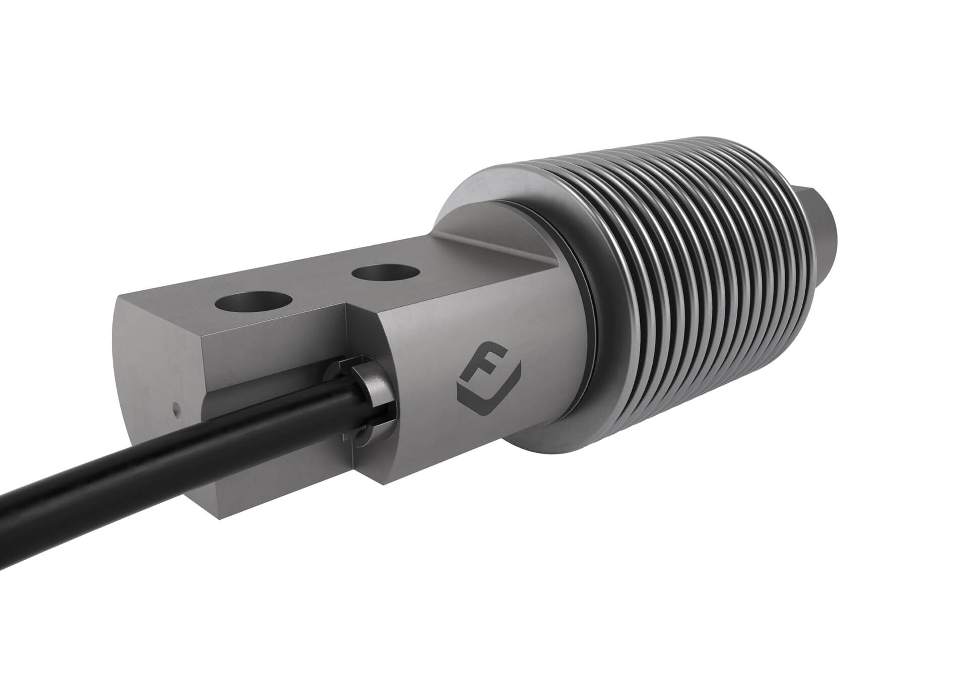
Installation and operation manuals. Flintec load cell supports are designed to avoid unwanted forces from affecting load cell performance.

Atex Operation Manual Rev94 Gb2 Cable Electronics
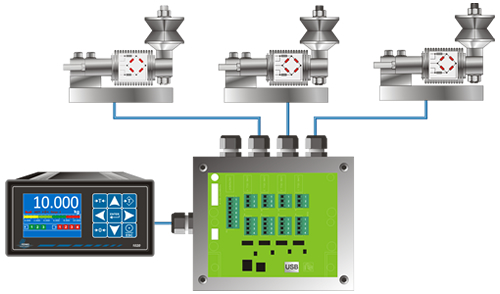
Flintec load cell wiring diagram. Variety of interface load cell wiring diagram. Models excitation excitation signal signal. It shows the elements of the circuit as streamlined shapes and the power as well as signal connections in between the gadgets. Shield sense sense. Electrical wiring and diagrams. The type 52 01 is a pre assembled weigh module with sliding system taking care of expansions.
For example di 145 di 149 and di 155 units are economical choices. It has a simple yet effective design which relies upon the well known transference between an applied force material deformation and the flow of electricity. A load cell is an electro mechanical sensor used to measure force or weight. The system is especially designed for using flintec beam. A wiring diagram is a streamlined standard photographic representation of an electrical circuit. The load cell field guide.
Product catalogs and literature. Wiring the amp to the dataq unit any suitable analog to digital converter may be used to convert the analog output of the load cell amplifier to a digital signal.


