Garmin gfl 10 pdf user manuals. Are listed in the product documentation.

Search Results For Catalog Category View 129 252 Desc 25
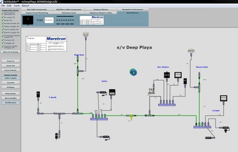
Garmin gfl 10 wiring diagram. Network cable to the expander. Contents gms 10 network port expander 010 00351 00 garmin marine network cable 320 00227 00 7 pin power cable 320 00023 05. 010 11057 00 ghc 10 nmea 0183 data cable. The gfs 10 must be connected to the power source of the boat optionally the gfs 10 can be connected to the fuel gauge on your boat to read fuel level data the bare wire cable contains the power and ground wires as well as the wires you connect to your fuel gauge follow the wiring diagram to complete the connections redwhite. There are four wires in the powerfuel gauge cable. Page 3 connecting the gfl 10 adapter to a nmea 2000 network after you have connected the gfl 10 adapter to the analog gauge or to the sender connect it to the existing nmea 2000.
Then your garmin marine network devices will be able to share information such as weather mapping and sounder data as well as position information. A redwhite blackwhite grey and brown. 010 11056 00 ecu power cable this cable powers the ecu. Gfl 10 installation and configuration instructions use the garmin gfl 10 adapter to adapt analog information provided by a fluid level sensor on your boat to your nmea 2000 network. The gfs 10 has two cables one for interfacing to a chartplotter and one for the powerfuel gauge. View online or download garmin gfl 10 installation and configuration instructions.
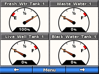
The alarm is wired to the ccu and provides audible alerts from the ghp 10. 6 pin transducer extension cable 010 10715 00 na6 10 no 20 ft. The gfl 10 allows you to observe fluid level information on compatible garmin display devices connected to your nmea 2000 network. The gfl 10 adapter allows you to observe fluid level information on compatible garmin display devices connected to your nmea 2000 network. The nmea 2000 analog adapters from garmin are easy to add to any existing marine network. Wiring the gfl 10 adapter to an analog gauge if your boat has an analog gauge representing the fluid level you can wire the gfl 10 adapter directly to the gauge.
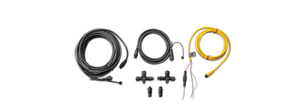
The redwhite wire is what supplies power to the gfs 10 sensor. Wire this to the battery of your boat as one of the last connections made in the ghp 10 installation. 6 pin transducer extension cable 010 10716 00 na6 20 no garmin 6 pin dual frequency 010 10272 00 50200 500w 4010 1500 dt 6 30 no 0 70 degree transom replacement for the dual frequency transducer included with many garmin units. A diagram on the product box shows which nmea 2000 components are included. Sample box diagram gfs 10 in the sample box diagram a complete nmea 2000 network is shown and the parts included with the sensor are shaded. In this example a t connector is included with a garmin gfs 10 fuel sensor.
