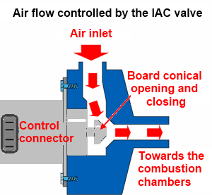
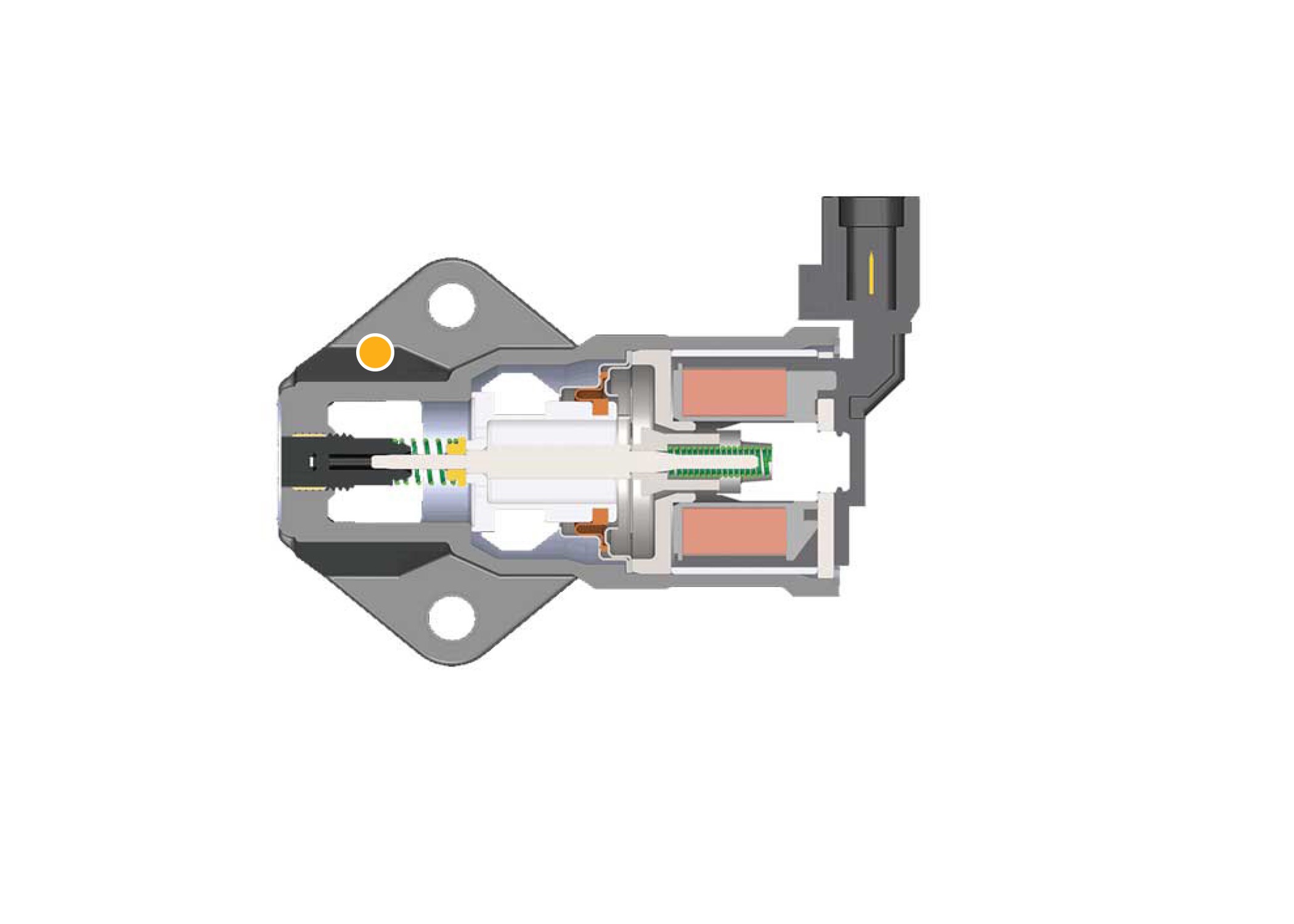
The way to tell if the motor is working is to reset the iac valve touch one battery cable to the other to short out the ecms memory then watch it closely on start up to see if the iac motor moves to a correct location to control the idle. Assortment of gm body control module wiring diagram.

Do You Have The Wiring Schematic For An 87 94 Chevy Need The
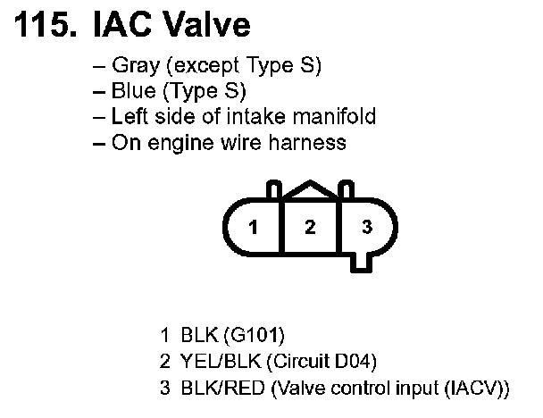
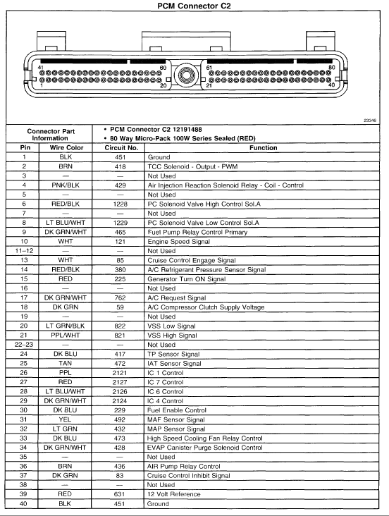
Gm iac wiring diagram. A1 grnwht this wire is used to energize the fuel pump relay. If your motor starts to idle at 650 700 rpm or so the iac motor should be working correctly. 558 408 j2a j2b j3 j4 connector and pin kit contains connectors and pins but no wiring. A5 brnwht sesservice eng soon light. The drive circuitry for such a motor requires a separate h bridge control circuit for each winding. If your rpms are the same both times your idle control valve isnt working.
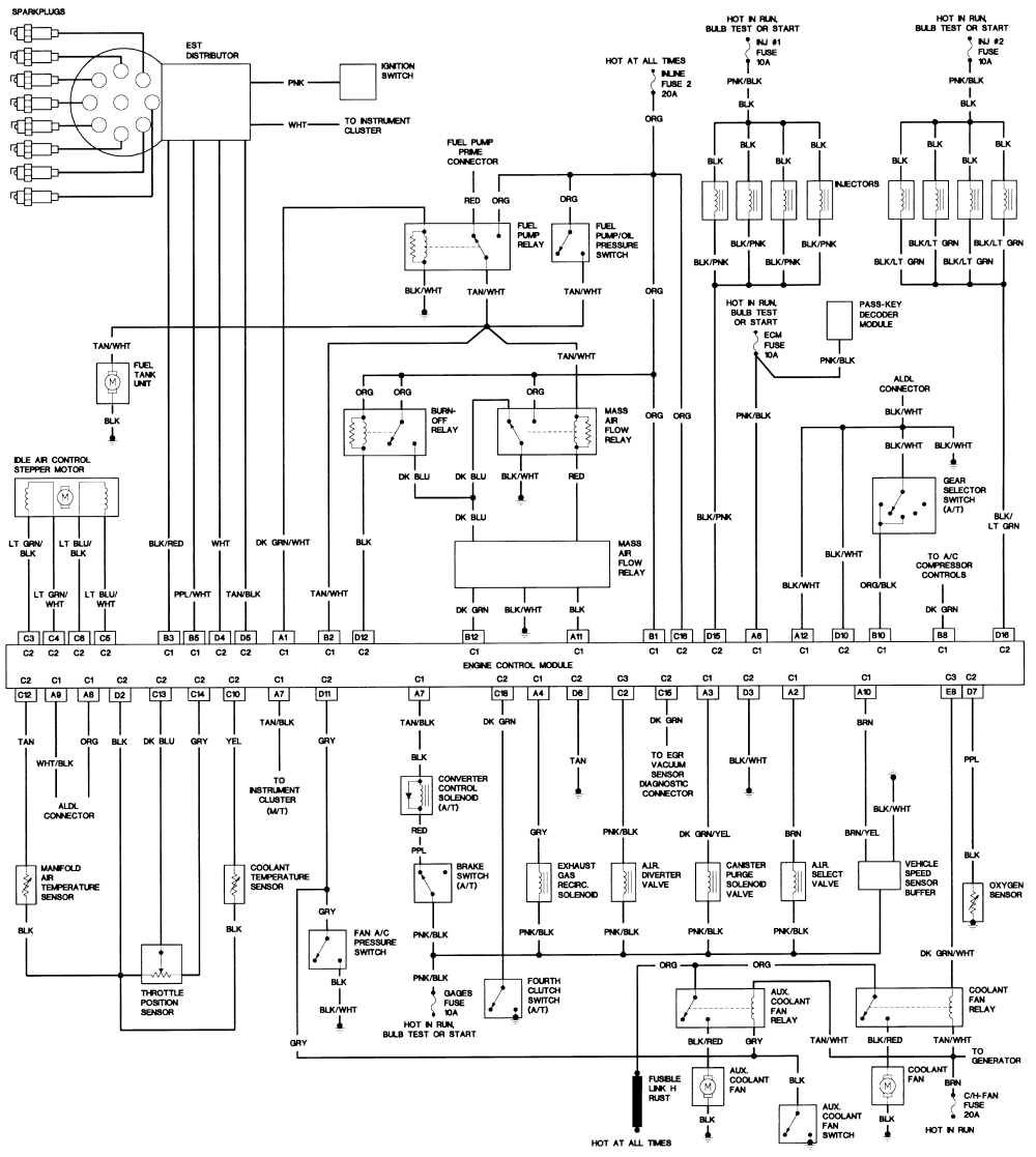
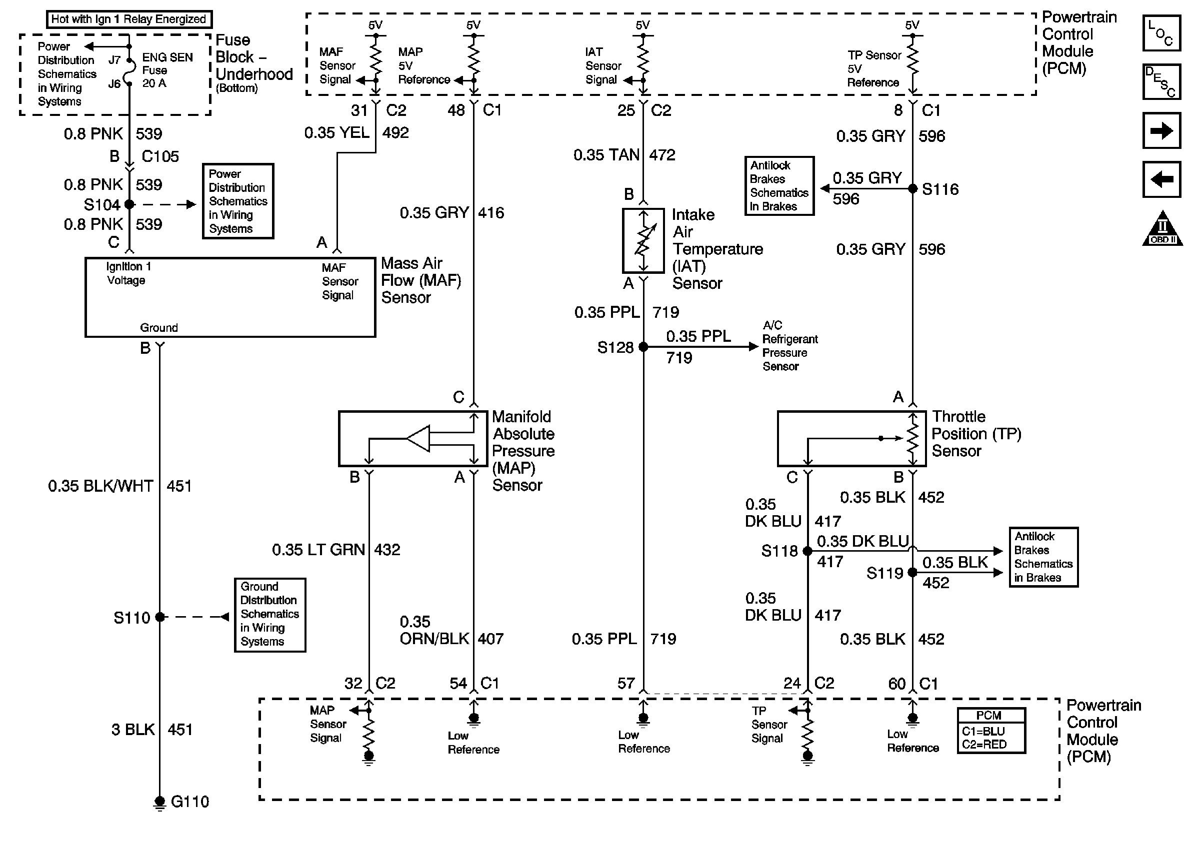
It shows the components of the circuit as simplified forms and the power as well as signal links in between the devices. Wiring diagrams gmc. This is a ground to turn on the light. If you run into an electrical problem with your gmc you may want to take a moment and check a few things out for yourself. On gm iac steppers the one coil usually has blue wires leading to it the other coil has green wires. 558 406 gm drive by wire harness complete terminated harness with j3 connector to operate late gm drive by wire systems.
C iac idle air control c fuel pump relay c the two fuel injectors c and the spark timing. Before you dive in with a multi meter you will want to obtain a free wiring diagram for your specific modelyou may need to locate a specific color wire and its exact location. Heres a list of the pins but they are also on the wiring diagrams above. For tips on how to check an idle air control valve in a gm or ford car read on. Once its disconnected tuck the wire out of the way restart your car and wait a minute or 2 before checking your rpms. A wiring diagram is a simplified standard pictorial depiction of an electrical circuit.
The schematic below shows how such a motor is wired. Block diagram acronyms individual components and their function schematic diagram. A2 not used a3 not used a4 gry to egr relayoptional this is a ground from the ecm to control the egr relay. Connections for each component and normal gm wiring color codes.


