Data output wire of interface module to vehicle data wire pin 2 until every other wire has been connected the harness has been plugged into the data bus interface dl module. Data output wire of interface module to vehicle data wire pin 2 until every o therwi as b n c d harness has been plugged into the data bus interface dl module.

Download Broan 7004 Wiring Diagram
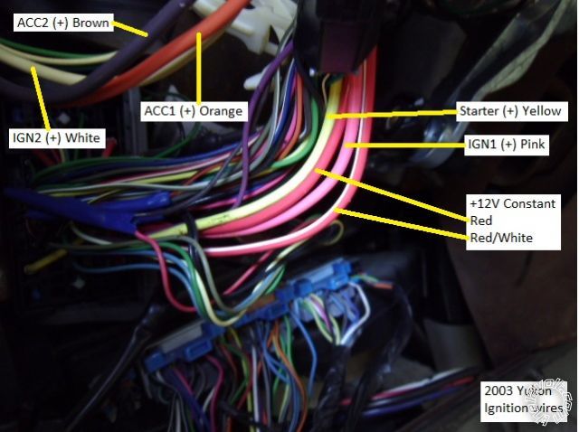
Gmdlbp wiring diagram. Pink and pinkwhite wires are only used when. If yours has the then use the white wire. The violetwhite wire will only be connected to the greenblack disarm wire in the 12 pin plug of the excalibur if the oem alarm sounds when remote starting the vehicle. You will only use one of them. Gmdlbp wiring diagram transponder bypass model gmdlbp xpresskit model gmdlbp gm doorlock alarm transponder passlock interface product features wire to wire patible with any type of remote car starter wiring diagram omega db gmdlbp sonic electronix omega omega db gmdlbp reviews wiring diagram legend warning the image depicted shows the. The orange wire will connect to the redwhite wire 12 pin harness of excalibur only on vehicles following platform 2 and 3 programming that also come with oem keyless entry.
Gmdlbp gm doorlock alarm transponderpasslock interface product features wire to wire compatible with any type of remote car starter w2w compatible with manufacturers anti theft content theft security systems maintains integrity of manufacturers anti theft immobilizer system no key required for operation nkr simple 2 step programming. Next to the wire color will be either a or a. Green 3 pin door lock harness to gmdlbp green note 1 the remote start has two parking light wires. Green lock input violetwhite not used pink dome light input from vehicle mode 6 determines input polarity note. Pink and pinkwhite wires are only used when. Green lock input violetwhite not used pink dome light input from vehicle mode 6 determines input polarity note.
On your vehicle wiring chart look up the wire for the parking lights.


