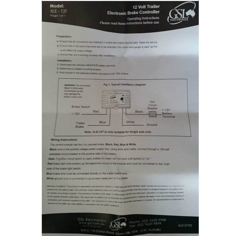
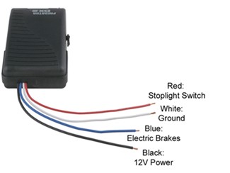
White ground wire is connected to grounded metal part of the trailer. Xle12 the micro size electronic brake controller is designed.
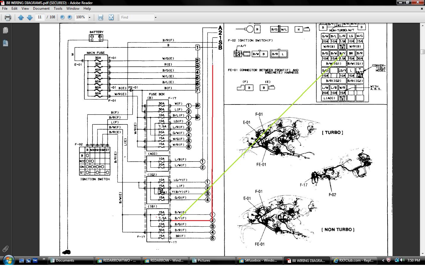
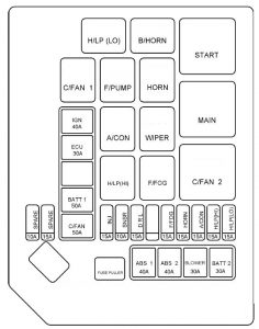
88 Mazda Rx7 Fuse Box Diagram Wiring Library
Gsl brake controller wiring diagram. Read and follow all instructions carefully before wiring brake control. Blue brake wire must be connected directly to the trailer brake wire. Wiring diagram xle 12 module 15a circuit breaker. Keep these instructions with the brake control for future reference. Installing a brake controller involves disconnecting the vehicle battery mounting the brake controller onto dash and plugging the unit in with a vehicle specific wiring harness. If your vehicle is not equipped with a plug and play harness you can also splice in wiring for connecting a brake controller.
Brake controller operating instructions please read these instructions before use the xle 12 is a compact rugged all electronic brake controller. Secure the brake controller into the mounting bracket. Wiring the 7 way trailer connector and brake controller. Break away systems may be added to the service brake circuit. Red brake light wire powers up the electronic circuit of the module and must be connected to the cold side of the brake light switch. 20 stage click knob with backlit led and push override.
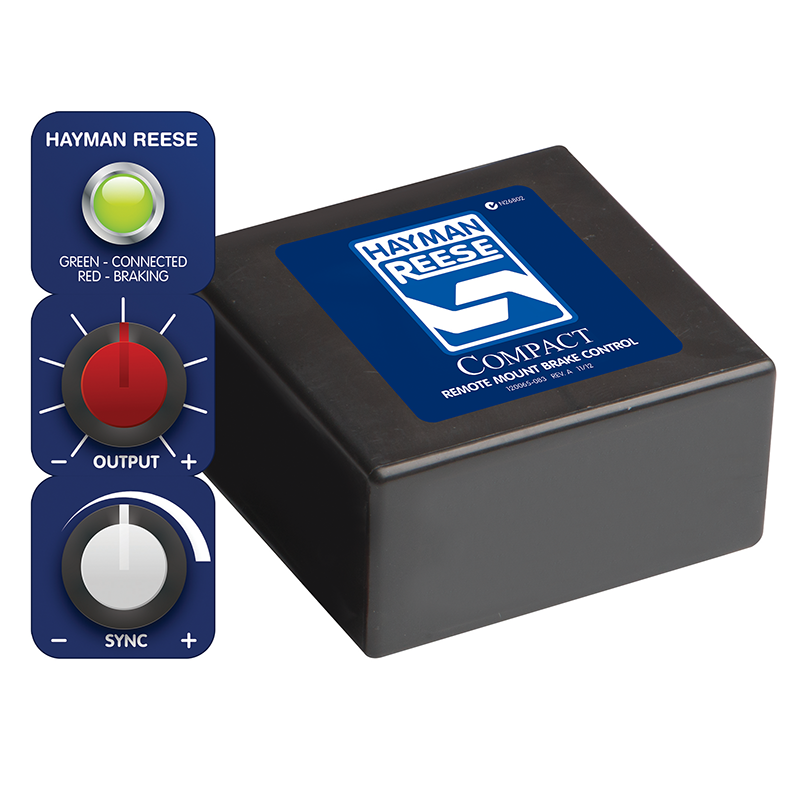
Easily adjustable via the remote control which can be located up to 1m from the controller. Ebc12 ebc24 digital display slide override with gradual progression multi level digital ramping rbc12 rbc24 compact discreete remote mounting brake controller. Auxiliary connection is optional it may be connected to any 12v to 24v constant power source or left unconnected. In this guide we cover step by step how to install a brake controller. Rbc 12 ng compact discreete remote mounting brake controller. The brake control must be installed with a 12 volt negative ground.
It is a compact rugged all electronic brake controller and is easily installed with the connection of four wires and the mounting bracket supplied. Return to the duplex cable under the hood where the brake wire now white needs to be separated from the 12 volt hot lead black. The rbc range is a new generation of brake controllers utilising microprocessor based technology. Redarc electronics have a large database of faqs tech tips wiring diagrams and how to guides. The four wires on the brake controller will be connected shortly. Wiring diagram to remote control black blue white red to vehicle brake switch cold side.
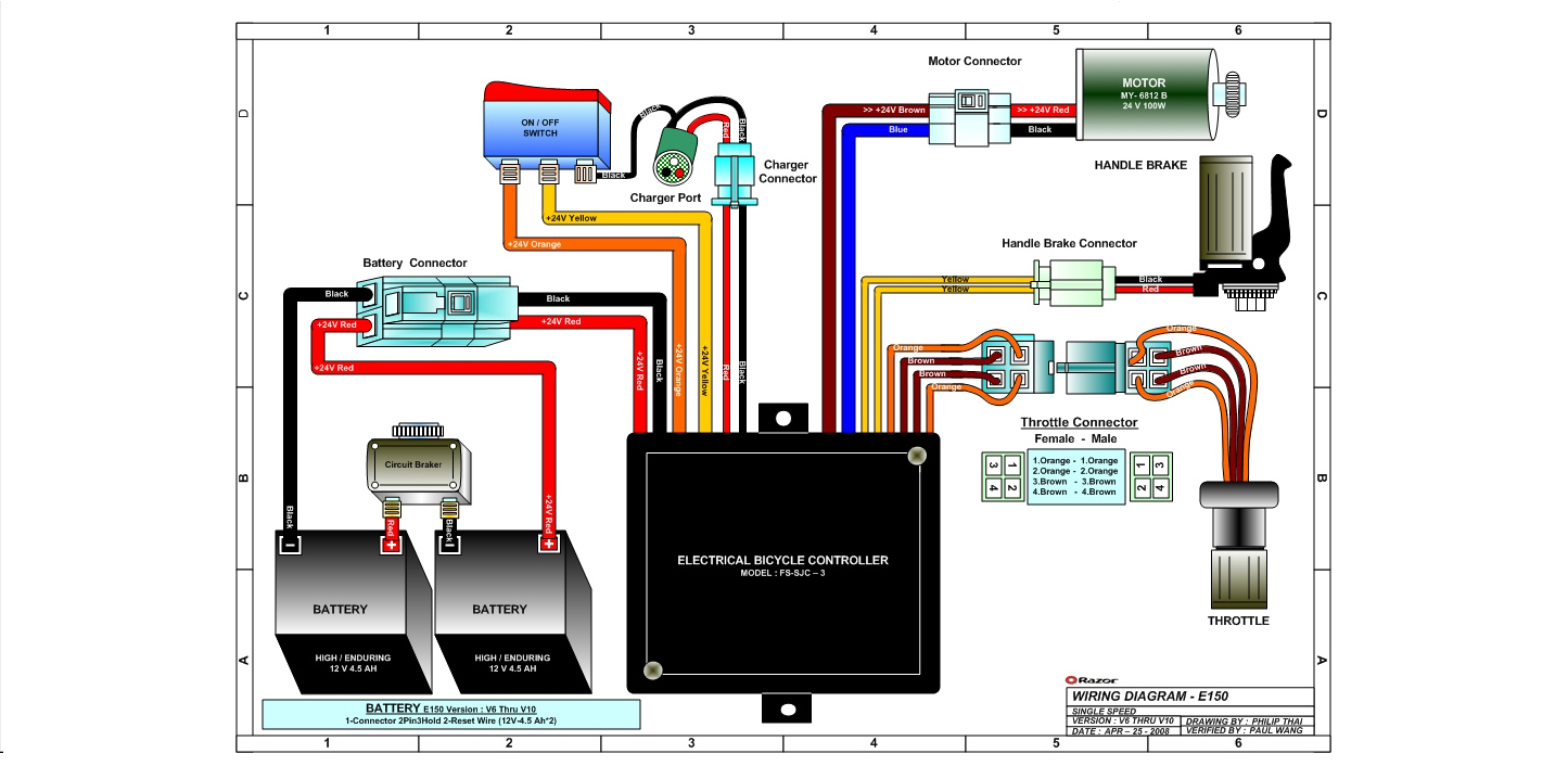
Electric brake controller wiring diagram. Elecbrakes is designed to operate 1 to 2 braked axles. 20 stage click knob with push override. Important facts to remember 1. Gsls rbc range is a new generation of brake controllers that operate in a pre set braking force utilising microprocessor technology. Available in both 12v and 24v gsls rbc range eliminates the need for a separate reducer on 24v systems.
Gsl electronics gsl warrants that its products will under normal use and service be free of defects in material and workmanship for a. Check them out today. Wiring instructions for electronic brake controls pn 4399 rev k generic wiring diagram read this first.
