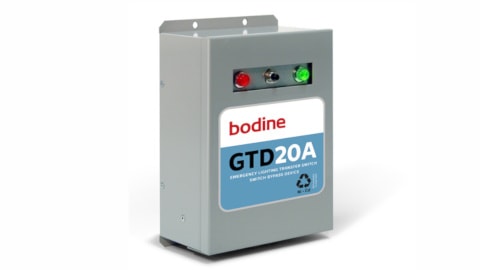
The gtd20a is not limited to emergency lighting applications. For generator or central inverter supplied lighting.

Rg 1986 Light Circuit Diagram Besides Bodine Emergency
Gtd20a wiring diagram. For additional applications and information contact the factory. Operation the gtd20a senses the loss of normal power and switches the lighting load connecting it to. For additional applications and information contact the factory. For additional applications and information contact the factory. The gtd20a is suitable for use in indoor and damp locations. The gtd20a is suitable for use in indoor and damp locations.
The gtd20a is suitable for use in indoor and damp locations. You can run a hot to the switch and then run two wires from there to the gtd20a. Wire gauges for all other connections should be sized according to total connected lighting load. Field installation indoor and damp full warranty. Page 5 drivers neutral dimmed hot gtd20a as a switch bypass device with a 3 wire dimming system note. Jumpers from 1 on t1 to 4 on t2 is made as well as 5 on t1 to 4 on t2suggestions.
Gtd20a automatic transfer switchbypass device. I have a joint made from the normal power hot. Neutral is also according to diagram. The gtd20a includes three dry form c contacts which allows the user a wide variety of wiring options. The gtd20a is suitable for use in indoor and damp locations. Ul listed for us and canada under ul 924 ul listed for the us under ul 1008.
Gtd20a jumper connections on t1 and t2 are contractor installed. When the generator or central inverter supplies ac power to the lighting fixture the gtd20a bypasses the local switching means or dimmer. For additional ap plications and information contact the factory. Operation the gtd20a senses the loss of normal power and switches the lighting load connecting it to a. The gtd20a includes three dry form c contacts which allows the user a wide variety of wiring options. The gtd20a includes three dry form c contacts which allows the user a wide variety of wiring options.
18 awg wire going to 1 on t2 and a 12 awg pigtail going to 3 on t1. For additional applications and information contact the factory. The wire that will be connected to t2 1 must come from the non emergency power source and must be connected to t2 directly. Wire gauges for all leads terminating at t2 should be 18 awg. If you have a switch in the t1 3 line then you need to tap power before the switch and run a wire to t2 1. The gtd20a includes three dry form c contacts which allows the user a wide variety of wiring options.
The gtd20a is suitable for use in indoor and damp locations. Operation the gtd20a senses the loss of normal power and switches the lighting load connecting it to a user designated emergency circuit. Wiring diagrams for ul 924 switch bypass applications the gtd20a uses an internal relay contact to control the ac power feeding the lighting load.


