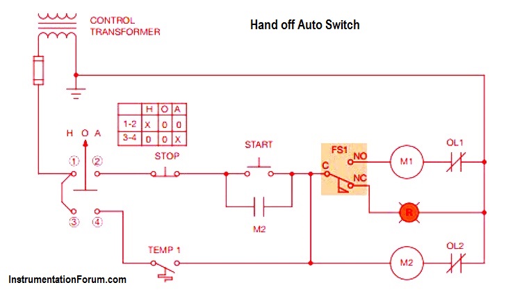
They can be used as a guide when wiring the controller. So if youd like to have the amazing images related to hand off auto wiring diagram best of just click save link to save these pics to your personal computer.

Automotive Switch Wiring Diagram Skoda Felicia Petrol Diesel
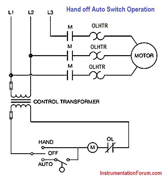
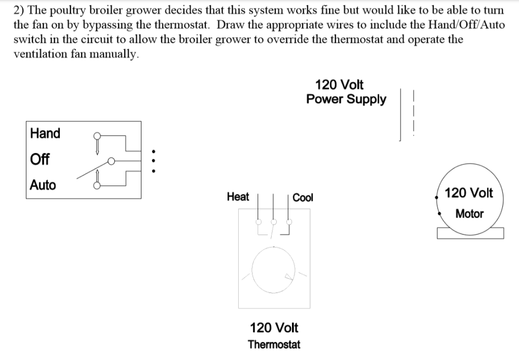
Hand off auto switch wiring diagram. Wiring diagram elementary diagram form f4t control circuit transformer and primary fuses type s ac magnetic starters class 3 phase additions and special features 3 pole. Hand off automatic controls recognize hand off automatic switches on a schematic diagram. Here is a picture gallery about hand off auto switch wiring diagram complete with the description of the image please find the image you need. 2 elementary diagram marked ol if alarm contact is supplied wiring diagram elementary diagram form c hand off auto selector switch mounted in cover fig553. The circuit shown in figure 271 permits a motor to be operated by a float switch or to be run manually. They show the relative location of the components.
Hand f auto switch wiring diagram hand f auto selector switch from hand off auto wiring diagram sourceresidentevilme. The autohandoff is sometimes an integral part of a factory pressure switch. These motor starters consist of an on off snap switch combined with a thermal overload device operating on the eutectic alloy ratchet principle. Hand manual control allows the pump to be turned on regardless of the position of the pressure switch. Wiring diagrams do not show the operating mechanism since it is not electrically controlled. Hand off automatic controls are used to permit an operator to select between automatic or manual operation of a motor.
Lever mounted on the front of the switch. Wiring diagram for a hand off auto switch travelwork for hand off auto switch wiring diagram image size 800 x 498 px and to view image details please click the image. Auto allows for unattended automatic starting of the compressor when the air pressure in the tank falls below the preset limit. Wiring diagrams sometimes called main or construc tion diagrams show the actual connection points for the wires to the components and terminals of the controller. These are prepared for save if you want and wish to get it. Figure 1 is a typical wiring diagram for a three phase mag.


