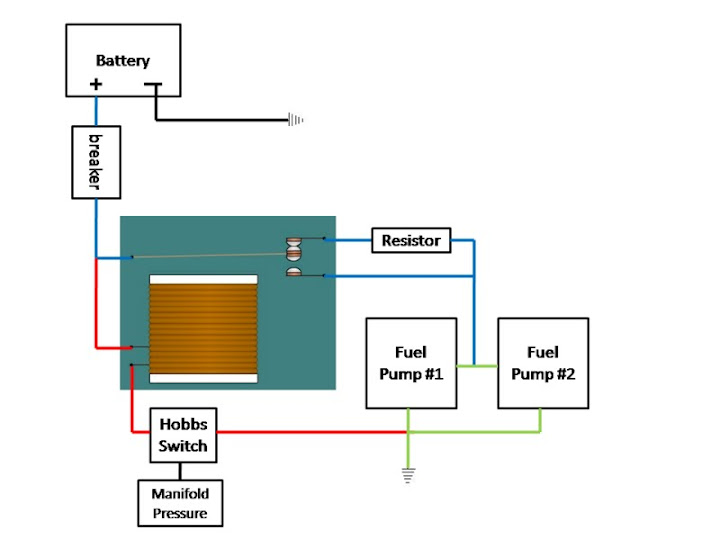
Explanation of wiring diagram 1. This circuit is wired the same way as the 3 way lights at this link.
Electric Fuel Pump Interrupt Page 1 Iboats Boating Forums
Hobbs switch wiring diagram. 8 the remaining brown wire from ecs bap goes to one of the hobbs switch terminals it does not matter which one for polarity is not important. Test the hobs switch adj and the other devices being conmtrolled on the bench firstmakes things easier. I found the connection boxswitch the old 3 wire cable for the hob is connected into. Three wire cable runs between the switches and the outlet. The source is at the sw1 where the hot is connected to. 3 way switched outlet wiring.
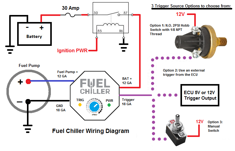
Instrument families 3 deluxetm instruments heavy dutytm heavy duty plustm instruments. The new 6400w induction hobs wiring diagrams give two options. If you plan to activate on of the fuel pumps with a hobbs pressure switch boost activated then you. I have seen enough people here asking questions over the years of how they should wire their dual fuel pumps setup. If you have other plans for your outputs you could also manually switch the second fuel pump or use a hobbs switch in a boosted application. When wiring a 2 way switch circuit all we want to do is to control the black wire hot wire to turn on and off the load.
In this diagram two 3 way switches control a wall receptacle outlet that may be used to control a lamp from two entrances to a room. Wiring diagrams 33 fuel pumps 34 35 2. Featuring wiring diagrams for single pole wall switches commonly used in the home. 93 notchback 383ci sbf highports 80mm turbo custom cam th400. Black wire power or hot wire white wire neutral bare copper ground. How to wire a single switch.
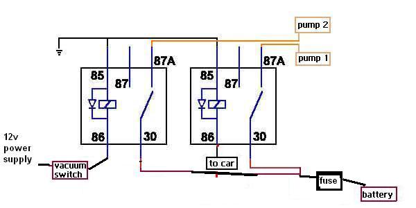
The front panel switch was loose so i brought a new one cooker control 45 amp double pole switch with mains socket i have wired up the new 4 wire cable into this no mains connection yet just did this so i could take a picture of how i think it should be. Circuit electrical wiring enters the switch box. I finally decided that since i just completed my custom dual in tank walbro setup setup that i would also take the time to make some diagrams since it is all fresh in my memory. The electrician opted for the 2nd option and wired the first part to the hob circuit off this existing spur which had a 13a switch now replaced with a 20a one and the second hob circuit to another 20a which is spurred off an existing spur to the. Switch wiring shows the power source power in starts at the switch box. A 1l1n and 2l2n wiring options.
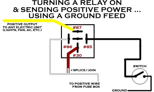
This simple diagram below will give you a better understanding of what this circuit is accomplishing. You can add a lamp to the power side of the circut and run that in the car so that you know when the value of the hob switch is met and the circut to the device that the hob switch controls is getting juice. 7 find a suitable location for the supplied hobbs switch near the vacuum tee and run supplied 532 vacuum hose from the installed vacuum tee to the barb fitting on the hobbs switch. Pressure switches 1617 temperature senders 17 temperature switches 17 hour meters dc hourmeters 1819 ac hourmeters 20 lcd hourmeters 21 lighting.
