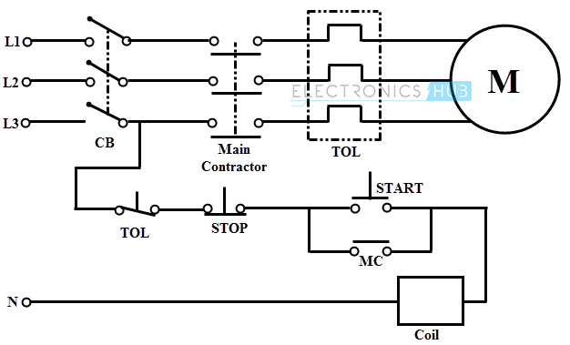
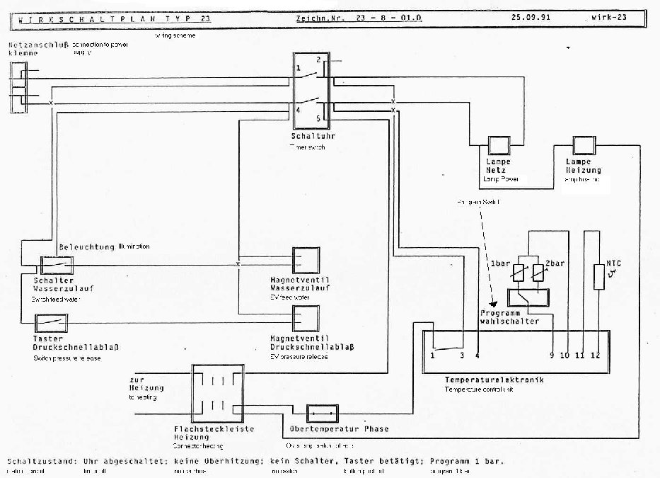
Basics 10 480 v pump schematic. Wiring diagram book a1 15 b1 b2 16 18 b3 a2 b1 b3 15 supply voltage 16 18 l m h 2 levels b2 l1 f u 1 460 v f u 2 l2 l3 gnd h1 h3 h2 h4 f u 3 x1a f u 4 f u 5 x2a r power on optional x1 x2115 v 230 v h1 h3 h2 h4 optional connection electrostatically shielded transformer f u 6 off on m l1 l2 1 2 stop ol m start 3 start start fiber optic.

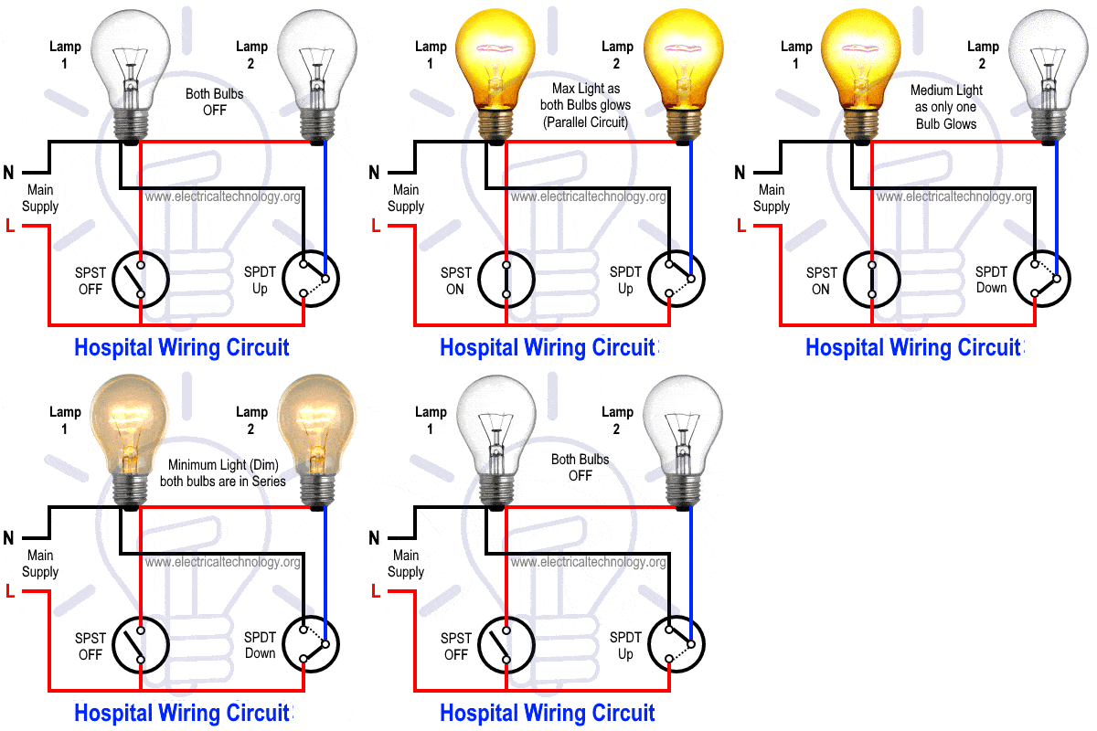
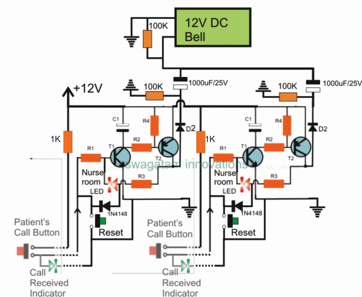
Hospital Wiring ह स प टल व यर ग
Hospital wiring diagram pdf. Basics 11 mov schematic with block included basics 12 12 208 vac panel diagram. Power terminal item 24 on internal component diagram location b4. Equipment to eliminate hospital electrical accidents. Therefore it must be properly maintained to. For electrical design criteria related to power supply see documents listed in table 9 1. Wiring for health care facilities nec article 517.
Leviton decora hospital grade duplex receptacles cableorganizer within hospital grade receptacle wiring diagram image size 632 x 419 px and to view image details please click the image. Basics 8 aov elementary block diagram. Hospital electrical equipment receives much physical abuse. Ii this edition of the uniform wiring guide is dedicated to the memory of the late roger bessinger who lost his battle with cancer on january 8 2010. However careful planning on the part of the consulting engineer architect contractor and hospital personnel can reduce electrical hazards to nearly zero. Each feeder shall be able to carry the full hospital.
Basics 7 416 kv 3 line diagram. Power terminal item 24 on internal component diagram location b3. Flexible power cords of appliances or. Basics 9 416 kv pump schematic. The wiring of the emergency system of a hospital shall be mechanically protected by installation in non flexible metal raceways or shall be wired with type mi cable. 23 normal hospital source.
Hospitals will be served by two primary service feeders each serving one end of a double ended substation or to a selector switch serving a multi ended network substation. Basics 14 aov schematic with block included basics 15 wiring or connection. Receptacles shall be listed hospital grade and labeled. To connect hospital alarms see the remote wiring diagrams fig. Power terminal item 24 on internal component diagram location b2. Basics 13 valve limit switch legend.
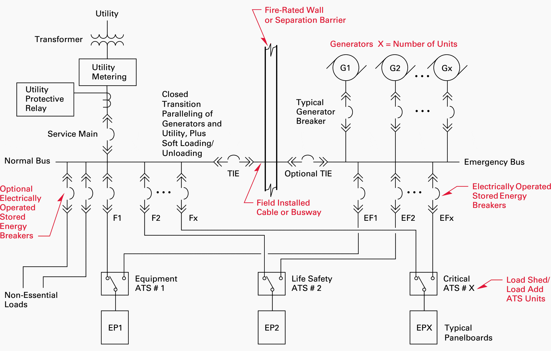
It is very important to make these specifications in the one line diagram. At least one shall be from the normal system or to a different transfer. Here is a picture gallery about hospital grade receptacle wiring diagram complete with the description of the image please find the image you need. Where installed as branch circuit conductors serving patient care areas the installation shall comply with the requirementsexception.


